


AimTrak Light Gun Without Recoil


![]()
- Emulates a USB mouse and game controller. No drivers required.
- Compatible with all PC OSes and Playstation 2
- Linux Support (Third Party)
- Works with all monitors including CRT, LCD, Plasma
- Accurate aim (after calibration) for games which do not have on-screen crosshairs.
- Up to 4 guns can be used together

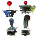
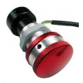
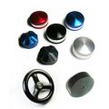
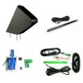
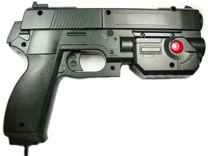
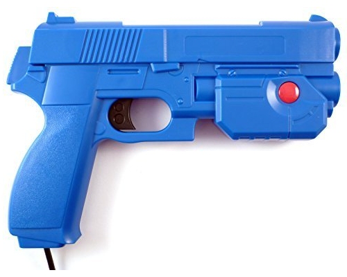
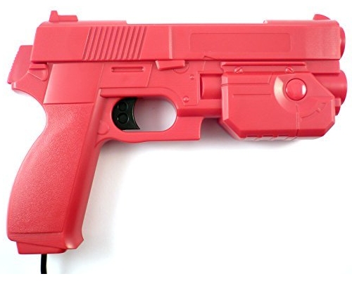
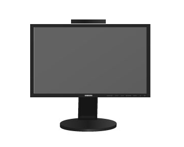
Arcade-quality gun with two buttons and trigger. Ready to play. Available in blue or black.
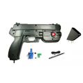
Box Contains:
- Complete gun with 2 buttons.
- 4 Meter USB Cable
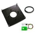
- LED Bar for mounting on top of monitor.
Download AimTrakConfiguration Utility Installer.
Download Detailed Setup Guide including MAME Configuration
Download Guide for operation on Playstation 2
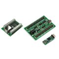
First, mount the LED bar on the top of the monitor using the adhesive pads. Note if you wish you can remove the casing from this unit for installation in an arcade cabinet. See the Aimtrak Module instructions for this.
Initial Check
- Plug the gun into a USB port and ensure the LED PCB is also plugged into a USB port.
- Movement of the gun should cause the mouse pointer to move. Its as simple as that! At this time the pointer may not move to the edge or may go off the edge and bounce to the other side. This is normal as the gun is not yet calibrated.
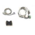
Recoil guns are shipped without recoil power supply.
The recoil power is routed via the connecting cable and the power supply needs to have a connector with outer diameter of 5.5mm and inner of 2.1mm.
The power supply needs to have the following maximum specs:,
24 volts 4 Amps, or 36V 3 Amps.
DO NOT use a supply with a current capability of greater than 4 amps as the mechanism relies on the current-limiting feature on the supply to prevent overload. If using two or more guns you will need one supply per gun.
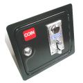
The center pin of the connector is positive. Outer barrel negative.
We have tested this 3A supply from an Ebay vendor and it gives stronger recoil than some 4A supplies: http://www.ebay.co.uk/itm/-/262181938884
Here is an Ebay USA link: https://www.ebay.com/itm/224253662140
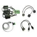
The pictures below show the cable connection and an example supply. This type of power supply is often available on Ebay.
Recoil power is adjustable in the Aimtrak Utility (see below)

|

|
Calibration is only required once. Settings are stored in the gun.
The gun must be held vertically during this process otherwise it will fail.
Hold the gun at the approximate location you will be using it. Note that the gun calibration must be done at the height the gun will be used at. This means if you intend to look through the gun-sights when playing you must do this when calibrating, or if you "shoot from the hip" you must do this when calibrating.
Players which are very different heights will not easily be able to share a gun.
- Hold the trigger for 5 seconds (this value can be changed, see later).
- The mouse cursor will eventually start to move and come to rest, pointing at a location near the top left corner of the screen, and begin to flash. Aim the gun at the cursor and pull the trigger again. The timing is not important as the cursor is an indicator only. The aim is the only important factor.
- The cursor will then point to a location near the top right corner. Aim at the cursor and pull the trigger.
- The cursor will then point near the lower edge of the screen. Aim at this point and pull the trigger. Note the position to aim is offset to the left of the screen center-line.
Calibration is done!
If any of the above steps fails, the cursor will continue to point at the required location and not advance to the next stage. If this continues to be the case you might need to install the Config software to diagnose the problem.
The most likely cause of failure to calibrate would be:
- Gun too close to screen. Min distance is approx 2 ft for 19in monitor and 3 ft for 28 in.
- LEDs not pointed in the approx direction of the gun.
Note that as calibration is performed at the corners, this is the most critical area regarding sensor detection.
In your game software, the game must be configured to use the mouse pointer as a gun.
This utility is not required for normal operation or for calibration. It is used for initial configuration (unless the defaults are used) and for troubleshooting.
Note the software requires the Microsoft .NET runtime to be installed on the PC.
Assigning ID.If you are connecting more than one gun to a PC, each one must have a unique ID.The ID is assigned by clicking on the "Assign ID" tab.
Sensor View Check. Clicking on this tab displays the Infra-Red LED as seen by the gun sensor.
Configure Controls: The trigger and up to 6 other buttons can be assigned as mouse buttons or gamepad buttons (1 to 8). Once selected, the APPLY CHANGES button must be clicked.
General Troubleshooting: Clicking on the "SHOW DATA" tab causes various information to be continously read from the device, including X and Y location.
Displaying Calibration Errors: Any calibration errors are displayed as text either in the "Display Data" tab screen or the "Sensor View" tab screen.
All configuration settings are stored permanently in flash ROM.
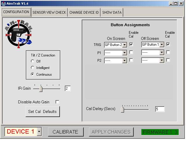
Below is a description of the controls:
DEVICE drop-down: This is used to select the device being accessed, from one to four.
CALIBRATE This button has the same effect as holding the trigger for 5 seconds. It initialtes the calibration process.
APPLY CHANGES Button: This must be clicked to apply any changes made in the above settings.
Button Assignments
These drop-downs allow configuration of the trigger and other connected buttons. Each can be assigned as a mouse left or right button, or a gamepad button. Every button has two possible assignments, an on-screen and off-screen setting. Off-screen would normally be used for "off-screen reload".
Each button has an "Enable Cal" check box which, when checked, allows this button to initiate calibration when held down.
After changing, APPLY CHANGES must be clicked.
Improving Tracking: Manual IR Gain
This setting controls the "brightness" of the internal IR sensor. The gain is automatically set, but this is a gradual "learning" process.
If you spend a few minutes, the result will generally be best if the gain is manually set. Once set it should not need to be changed unless operating distance is substantially changed.
You can disable automatic gain control by checking the Disable checkbox.
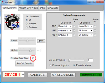
When automatic gain control is disabled, you can set the gain to one of 5 values with the slider. Check each value for the best performing setting.
After changing, APPLY CHANGES must be clicked each time.
Trigger Calibration Delay
This slider defines how long the trigger (or other buttons with "Enable Cal" checked needs to be held to start the calibration process.
After changing, APPLY CHANGES must be clicked.
Tilt/Z Axis
These 3 check boxes define the way the gun responds to being tilted left/right.
OFF:This setting disables all tilt functionality. This means the cursor will move when the gun is tilted. This should be used only for "air mouse" or other uncalibrated applications. It gives the smoothest cursor movement but is not accurate to "line of sight". It might also be useful in gun applications which have a visible "cross-hair" target which does not require any visual aim of the gun.
INTELLIGENT:This setting compensates for tilt by averaging and then applying the compensation when it decides is the best moment to do so. This means the cursor may temporarily lose accuracy when the gun is tilted left/right but in normal gaming use this is not an issue.
CONTINUOUS:This setting causes tilt compensation to be constantly applied. This may result in a slightly choppier cursor than the above two settings.This is not an issue when the cursor is not visible, which is in most gaming situations.
Regardless of the above, the gun will not function reliably if excessively tilted left/right.
After changing, APPLY CHANGES must be clicked.

This display shows the Infra-Red LED as seen by the sensor. Note that this shows the raw uncalibrated display so will not correspond to cursor location on the screen.
This screen is used to check if the LED bar is in a location which can always be seen by the gun, in all aiming directions.
This display can be used to determine why calibration is failing. You can start the calibration process from this window. When you aim at the flashing cursor each time, check the display as well. If the red dot is not visible, calibration will fail. You can move the gun slightly to find which direction the error lies.
Failure to calibrate is usually caused by either being too close, or an obscured or faint LED signal. This display will help to identify the problem.
On this window you can change the ID of the device to one, two, three or four. This is required to be done if you have more than one device connected. After the device is re-assigned, it will "disappear" from the PC for a few seconds and re-appear as a new device with its new ID.
This tab is also used to upgrade firmware.
Upgrading Firmware
The latest version is now included in the installation files of this Aimtrak Configuration Utility.
- The PC will detect a new USB device and a driver will be automatically installed.
- The upgrade program will start. Click on "Select Firmware File" and navigate to the UFW file. This will normally be contained in the install folder of the program.
- The firmware should download.
- After download, the device will reset. You should see "Device not found" on the bottom line. The device should now be back in normal operating mode.
Dynamic Data
This section displays data read from the device such as X, Y location, This is used for troubleshooting and support purposes.
This section also contains a display of any errors encountered during a calibration process.
Calib Data
This section displays various unchanging data which is data stored as a result of running a calibration process. It is refreshed every 5 seconds but should not normally change after the initial read or calibration.
All the other settings are also read from the device every 5 seconds.
Please bear in mind the Aimtrak will not work with the LED bar mounted on top of the Arcade Legends cabinet
as this places it too far from the top of the screen. It needs to be mounted about the screen.
There is an excellent guide to using the Aimtrak with Arcade Legends here:
AimTrak Light Gun Legends Ultimate Guide [ Wagner's TechTalk ]
Also thanks to Rafael Monroy (RaphSeraph) for this Guide to installation and setup on an Arcade Legends
Recent versions of MAME and Windows have changes which mean it is advisable from the outset to create a custom control file for MAME.
The MAME official documentation for this is here
This also prevents devices from being swapped around on reboot.
The following is an example of the contents of a control file which identfy two guns which have previously been configured as ID #1 and ID #2:
<mameconfig version="10">
<system name = "default">
<input>
<mapdevice device="PID_1601" controller="GUNCODE_1" />
<mapdevice device="PID_1602" controller="GUNCODE_2" />
<mapdevice device="ATRAK Device #1" controller="JOYCODE_1" />
<mapdevice device="ATRAK Device #2" controller="JOYCODE_2" />
</input>
</system>
</mameconfig>
Lets look at where these entries come from.
The IDs such as "PID_1601" are part of the ID which Windows generates for all connected devices. Only this part of the full device ID needs to be used as MAME will scan the full string for a match.
The full ID is different for every PC but the "PID_1601" appears on all PCs for gun #1 as this comes from the gun itself.
The "PID_1601" and "PID_1602" refer to the mouse funtion of the two guns.
The "ATRAK Device #1" and "ATRAK Device #2" refer to the gamepad function of the two guns. This configuration includes these, as buttons/trigger can be configured as gamepad buttons.
These IDs can be seen, if you need to, in the "hardware Properties" of the device in Device Manager or by launching MAME from a command prompt using "MAME -v". But in fact these will always be as shown for guns with IDs 1 and 2.
The control file needs to be saved with an extension of "cfg". The name (without the extension) needs to be added to the Mame.ini file in the line "ctrlr.....". If you dont have a Mame.ini file, it will need to be created using "mame -cc" from a command prompt.
Relevant mame.ini file entries are:
# CORE INPUT OPTIONS
ctrlr <name of your control file>
lightgun 1
joystick 1
multimouse 1
offscreen_reload 1
# INPUT DEVICE OPTIONS
dual_lightgun 0 (this is counter-intuitive but correct!)
Two excellent videos which have been produced by "Maverick's Arcade" which demonstrate MAME configuration:
General setup of gun and MAME:
https://www.youtube.com/watch?v=VCbc3X2qFI8
Detailed configuration of multiple guns and avoiding device swap:
https://www.youtube.com/watch?v=YmjfwLuZ_X0
Other emulator notes:
Dolphin: In the control settings use Cursor X-, Cursor X+, Cursor Y-, Cursor Y+ rather than the Axis of the mouse.
We are grateful for the third-party support of the Aimtrak guns under Linux, which can be found on developer Katie Snow's page here.
Common Issues
95% of issues are cause by mis-placement of the LED bar.
The bar must be the correct way up (sticky pads on the underside)
The bar must be within 1-2 inches (10cm) from the top of screen.
The gun will not work if the bar is located on the top of a cabinet which has a marquee.
Extra Check: LED Bar Verify
This is an extra check we have added owing to a few recent reports from customers of mis-aligned LEDs.
Use a digital camera or phone and first make sure it can see infra-red light by aiming a TV remote and check it sees the beam when buttons are pressed. (Some recent phones have IR filters)
Check the LEDs of the bar appear as shown in the picture below, when the camera is held in the approx location the gun will be used in. They should be very bright and the right-hand one slightly dimmer.
If they do not appear as in the picture, remove the screws from the base of the bar and re-check without the case. If this cures the issue the LEDs may be bent too far down. They should be bent approx 16 degrees, so they aim roughly at the gun. Email for advice if necessary.
Step 1: Light Interference Check
Disconnect the LED bar so this is disabled.
Aim the gun at the screen and move to all screen areas. There should NOT be any visible cursor movement. If there is any movement this indicates the gun is picking up an extraneous infra-red light source such as sunlight from a window behind the cabinet, a window reflecting in the screen, or a conventional or halogen light within view of the gun, or reflection of a light. Fluorescent/CCFL lamps are not a problem.
Step 2: Range Check
Use the test utility software and open the "Sensor View Check" tab.
Move the gun over all screen areas. The red dot should move. The movement is "backwards" as this is the view which the gun is seeing, not the result of the data moving the mouse pointer.
The dot should be visible and red in color when the gun is moved over all screen areas.
There is also another special check which is useful. When aimed at the bottom center of the screen, the "Visible Points" should show "Two". Both ends of the LED bar need to be seen by the gun at this location otherwise calibration will fail.
Results are as follows:
- Dot goes off the edge when the gun is still within the screen area: Gun is too close to the screen, or LED bar too far away from the screen edge
- Dot turns orange or disappears while away from the edge: Infra red light too dim. Gun too far away, LED bar not aimed at gun (this can be checked using any digital camera, as these can see IR light).
- "Visible Points" does not show "Two" when aimed at bottom center of screen: LED bar out of line, insufficiently powered, Gun too close or far from the screen.
Download AimTrakConfiguration Utility Installer.
Download Detailed Setup Guide including MAME Configuration