
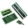
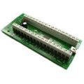


PacLED64


Features:
- 64 LED channels with 256 brightness levels for full RGB color mixing
- NEW FEATURE! Can be set to flash any or all LEDs at one of 3 rates, without PC control.
- Can be used with single-color or RGB LEDs (RGB use 3 channels)
- Constant current negates the need for resistors for each LED
- Can be used with LEDs with inbuilt resistors if required
- 128-command flash storage for “attract-mode” sequences which run immediately on power-up with no PC present
- Supports single-command fades with preset speed on-board. Multiple fades can overlap
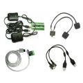
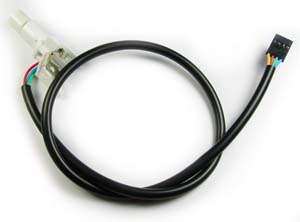
- Comes with power cable for plugging into a PC disk drive power connector, and USB cable
- User-assigned IDs allow multiple boards to be connected
- Extensive software support including test application, Software Development kit for adding support to your own programs, and LedBlinky third-party software
- Compact modular connectivity. Our Ultralux RGB pushbuttons simply plug in. Other harnesses and connectors available.
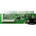
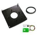
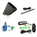
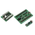
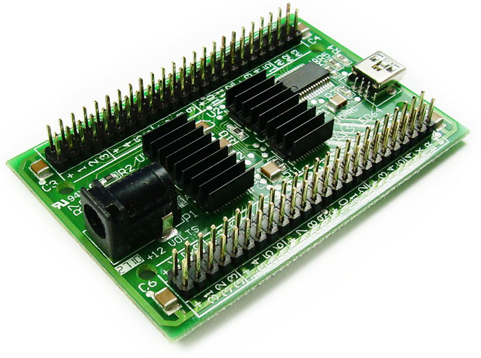
- PacLED64 Board.
- USB Cable
- Power cable for connection to PC HDD power
- 2 x 48-way empty connector housings. Wires with crimp contacts (ordered separately if required) push into these.
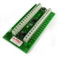
Connecting LEDs
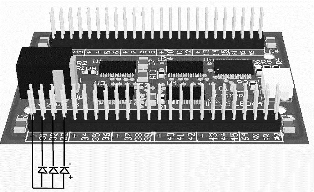
Each LED must have its negative connection (cathode) connected to one of the numbered pins 1-64.
Each LED must also have its positive (anode) connection connected to one of the supply pins marked “+”. Note it does not matter which of the “+” pins you use as they are all connected together on the board.
You can daisy-chain multiple LED + connections and connect to one + pin.
The picture below shows a schematic representation of three LEDs connected to channels 31-33
Note that if using Ultimarc Ultralux RGB pushbuttons, no additional connectors nor wiring is required. These have built-in wiring and connectors available in 2 lengths.
The pins labeled A1-A6, PR, NX and GND are for future customized OEM versions of the board and are not used in the standard version.
The following are available in our online store:
|
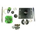
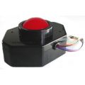
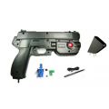
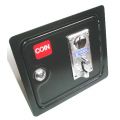
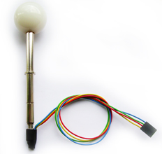
Illuminated joystick handle for Servostik and J-Stik. Plugs directly into this board. |
 |
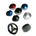
RGB LEDs for Ultralux buttons. Available in 2 wire lengths. See the Ultralux product page for more info. |
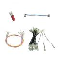
|
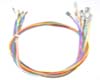
These are 600mm long wires which push into the housings, above. The other ends have 6.3mm or 4.7mm push-on terminals. If required, these can be cut and shortened, which requires a new crimp terminal to be fitted. Use for the channel (negative) connections of individual LEDs. If using with single-color Ultralux buttons, order the 6.3mm connector size. In packs of 10 |
|
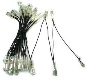
Pre-made harness with 32 x 6.3mm or 4.7mm connectors fitted. Ideal for connecting all positive connections of LEDs to one of the “+” pins on the board. If using with single-color Ultralux buttons, order the 6.3mm connector size. |

|
Use if shortening the pre-made wires. 6.3mm for Ultralux pushbutton LEDs. Packs of 100 |
| For connecting Ultralux RGB LEDs: | Nothing extra required |
| For connecting Ultralux single-color LEDs: | Order one 600mm wire per LED (wires are in packs of 10). Order daisy-chain for + common for each 32 LEDs |
| Other LEDs: | Order as Ultralux but may need to cut off the push-on connector at the LED end. |
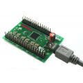
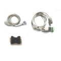
Connecting Power and USB
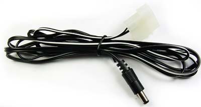
The PacLED64 is supplied with a power cable which plugs onto a spare PC power supply hard drive power connector. This supplied 5 volts to the board.
Also, connect the USB cable to a USB port on the PC.
Alternative Power Options
The LED power connector can be powered from another source such as a wall-plug power supply. The voltage required depends on LEDs being used but all LEDs supplied by Ultimarc require 5 volts and the supplied power cable is pinned for 5 volts.
Current requirement is 0.02 amps X number of LEDs. Note each RGB LED counts as 3 LEDs.
Ensure CENTER pin on the connector is 5V, BARREL is ground.
Connector is 5.5mm diameter. 2.1mm pin.
When you power on the PC, the board will immediately run a script which is pre-loaded in flash. If you have overwritten this with your own script, this will run. The pre-loaded script causes all LEDs to sequence in a fade up/down “wave” from 1 to 64. Scripts are repeated continuously.
When a command is sent by the PC via USB, the script stops running and the command is processed. The script is then not run again until the next power-on.
Download the application here
This app is used for the following:
- Testing LEDs and connections by turning LEDs on/off or setting to a specified brightness.
- Creating simple “attract mode” scripts and storing in the on-board flash ROM
- Assigning an ID to board, when using more than one board
Settings Tab
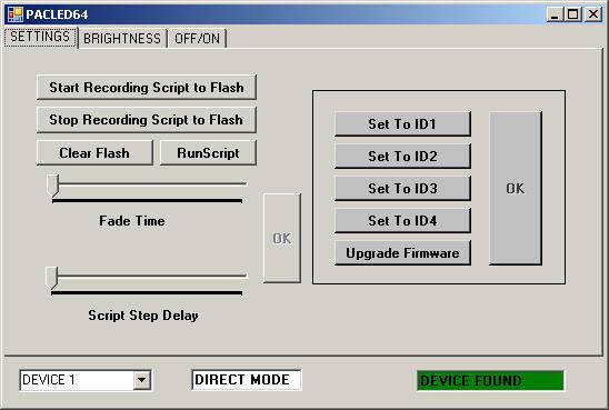
Start/Stop/Run Script
When clicked, all subsequent commands will be stored in on-board flash. Next time the board is powered on, the script will run and loop forever until a command is sent from the host via USB.
Clicking “Stop Recording” will end the script storage.
Clear Flash
This will cause any stored script to be deleted, so on next power-on, nothing will happen until the host sends commands via USB.
Fade Time
This adjusts the time taken to perform a fade. A fade occurs whenever the state of a LED changes, ie its brightness is changed or switched off/on. This setting affects all subsequent state changes. This can be stored in scripts.
Script Step Delay
This adjusts the time interval when scripts are being executed. This can be stored in a script. This is not relevant when sending direct commands from the host.
Brightness tab
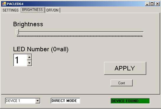
On this screen, the brightness of any of the 64 LEDs can be set. The command is executed immediately by the board, and if you are storing a script, is also added to the script.
On the latest version (requires latest firmware) the LED(s) can also be set to flash at one of 3 rates on this screen.
Off/On Tab
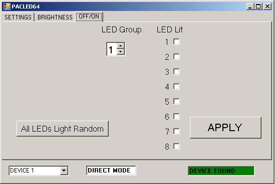
On this screen, a group of 8 LEDs is set to a pattern. The LEDs are either fully off or fully on. There are 8 groups of 8 LEDs. Also, all LEDs can be set to a random pattern.
The command is executed immediately by the board, and if you are storing a script, is also added to the script.
Ultimarc LED and output controllers have great software support, including PC and Linux software and our own SDK which enables easy addition of output control to your own programs.
Also a Linux library is available. See our Programming tab above.
 For Windows
 For Linux (Retropie). Thanks to RetzNutz.
 LED control for advanced users.
There are more details and screenshots of third party software on our PacDrive page
This is a third-party application available in free or paid versions. It is actually a suite of programs enabling configurations to be stored, animations to be created, and has special MAME features.
Note that LEDBlinky supports direct control of the board via USB only. It does not support creation of scripts for storing on the board.
Version 5.0 required.
- With RGB LEDs, you can specify colors for individual controls or using a pre-defined colors.ini file. Colors or intensities can also be customized on a game-by-game basis.
- Use audio output (music or game sounds) to blink, fade, or animate LEDs – great for use with Jukebox software.
- Blink and speak front-end UI controls by pressing a pre-defined “Help” button.
- Blink and speak controls when pausing a game and/or play a LED animation (selected, random, random montage) or use audio output (music) to animate the LEDs. This is a MAME only feature.
- Flash start buttons when credits are available - this is a MAME only game dependent feature.
- Light start and coin buttons based on active player count for the current game.
- Flash all or active buttons when any is pressed.
- Full support for other MAME Outputs - light LEDs based on any output. Outputs can be linked to controls (P1_Button1, P2_Button2, etc.) or directly linked to a Device/Port.
- Extensive audio animation options let you completely customize how the LEDs blink to music or game sounds.
- When starting a game, LEDBlinky can play a LED animation (selected or random), speak the game name, speak each button “action” while blinking the button in its correct color, speak the primary controls, and speak a custom message. When speaking the game name or custom message, LEDs can blink in sync with the speech.
- While playing a game, LEDBlinky can play a continuous LED animation (selected, random, or random montage) or use audio output (game sounds) to animate the LEDs. The LED animation will only effect unused controls.
- See the LEDBlinky website for all details.
An SDK is available which includes a DLL to provide an API to enable LED control in your programs. The SDK includes the DLL, plus example source code showing its use. A test program for checking operation of the DLL is also included.
The SDK is detailed on our Programming tab above.
As most third-party software and our SDK is cross-product, we have placed all details on this page.
Our PAC-Drive board can also be used for simple low-cost On/Off LED control.
| No of Channels | Dimming | Current | Can control | Voltage | Flash Storage | |
| PacLED64 | 64 | Yes | 20mA constant | LEDs only | 12 v max | Yes |
| PAC-Drive | 16 | No | 500mA (max) not constant | All devices | 48v max | No |
ULTIMARC PROGRAMMERS PAGE
This page contains details of software available for all products for controlling output devices, reading inputs programatically and other usage.
Output control:
- PacLED64
- PacDrive
- U-HID PC Controlled LEDs
- I-PAC Ultimarc I/O Controlled LEDs
- NanoLED
- USBButton
- Servostik 4-8 way switching
Input:
- USBButton Read State
Demo Code:
- PACDriveDEMO with source. Covers all products above and includes a GUI control panel
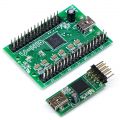
Linux Library and command line utilities developed by Katie Snow
The Ultrastik360 is accessible via DirectX/DirectInput, an unmanaged C/C++ programming interface. Using this interface in .NET requires knowledge of C++ by writing managed wrappers. The open source library from http://sharpdx.org/ did exactly that, so using the stick in .NET is now done in a few lines of code.
This Example shows a simple example in C#. The minimum needed parts of the SharpDx library (2 dll’s, 700kb) are automatically downloaded and managed via NuGet when you compile first time.
- SetupTestSharpDx.exe file is a full automatic inno-setup which places the required binaries in ‘program files’ (exe with some dlls)
- The binaries file contains the same files, but without setup. Unzip them anywhere
- The source file contains a readme, the visual studio 2013 C# project with all necessary source files (Framework 4.5.1).
All our firmware-upgradeable USB products use the same method for upgrade.
This is how it should work:
- Firmware upgrade requested from the appropriate utility (WinIPAC, Ultramap, U-Config etc) The utility must be right-clicked and "run as administrator".
- A driver is pre-installed automatically. This is the only time any of our products require a custom driver.
- The device is shut down by the utility and then resets as a different device, which is known as a "Firmware Upgrade Device".
- This new device should appear in Device Manager, if the "USB Controllers" entry is expanded.
- A program called "uupload.exe" is started automatically by the utility. The utility is then closed down.
- The "uupload.exe" window should appear and a "device detected" message should appear.
- The firmware file is selected from this window and upgrade should proceed. Do not be concerned if the progress bar does not show.
- The upgrade should take max 5 minutes. After that, the device is reset back into normal operation mode, and at this point the uupload program can no longer see it, and should display "No device detected or upgrade complete".
Uupload.exe cant find the upgrade device
The most common reason for this is the custom driver install has failed. This can be checked by starting device manager and expanding the "USB Controller" entry. The device might be showing with an error, or there might ne a new device somewhere else in Device Manager which has failed to install.
The fix for this is as follows:
- Download the manually-installed driver from the link in the section below and run "setup" located in the setup folder. NOTE: Must be right-clicked and "run as administrator".
- Right click on the failed device and "uninstall"
- Click "Scan for new hardware". The driver should install.
- Re-run the "uupload.exe" program which is located in the install folder of WinIPAC, UltraMap, U-Config etc, and re-try the upgrade.
Firmware upgrade locks up or fails to finish, resulting in stuck in upgrade mode
Simply re-run the "uupload.exe" program which is located in the install folder of WinIPAC, UltraMap, U-Config etc, and re-try the upgrade.
The various utility programs for our devices incorporate a firmware upgrade feature. This requires a driver (the only time a driver is required). The driver installs on the fly but should a manual install be required, this installer does this. Run the Setup program in the Setup folder.