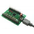


U-HID
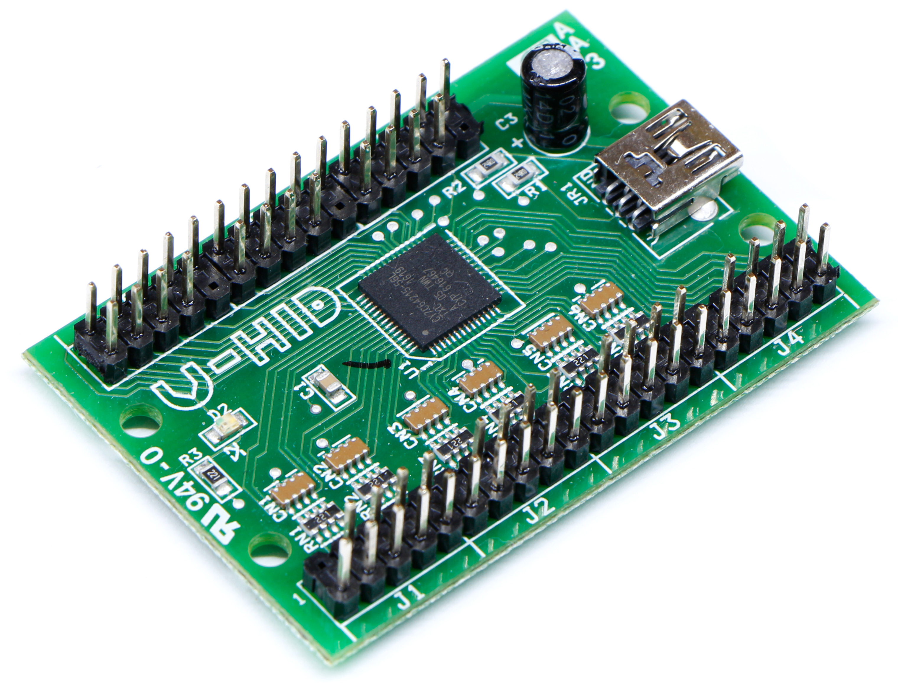
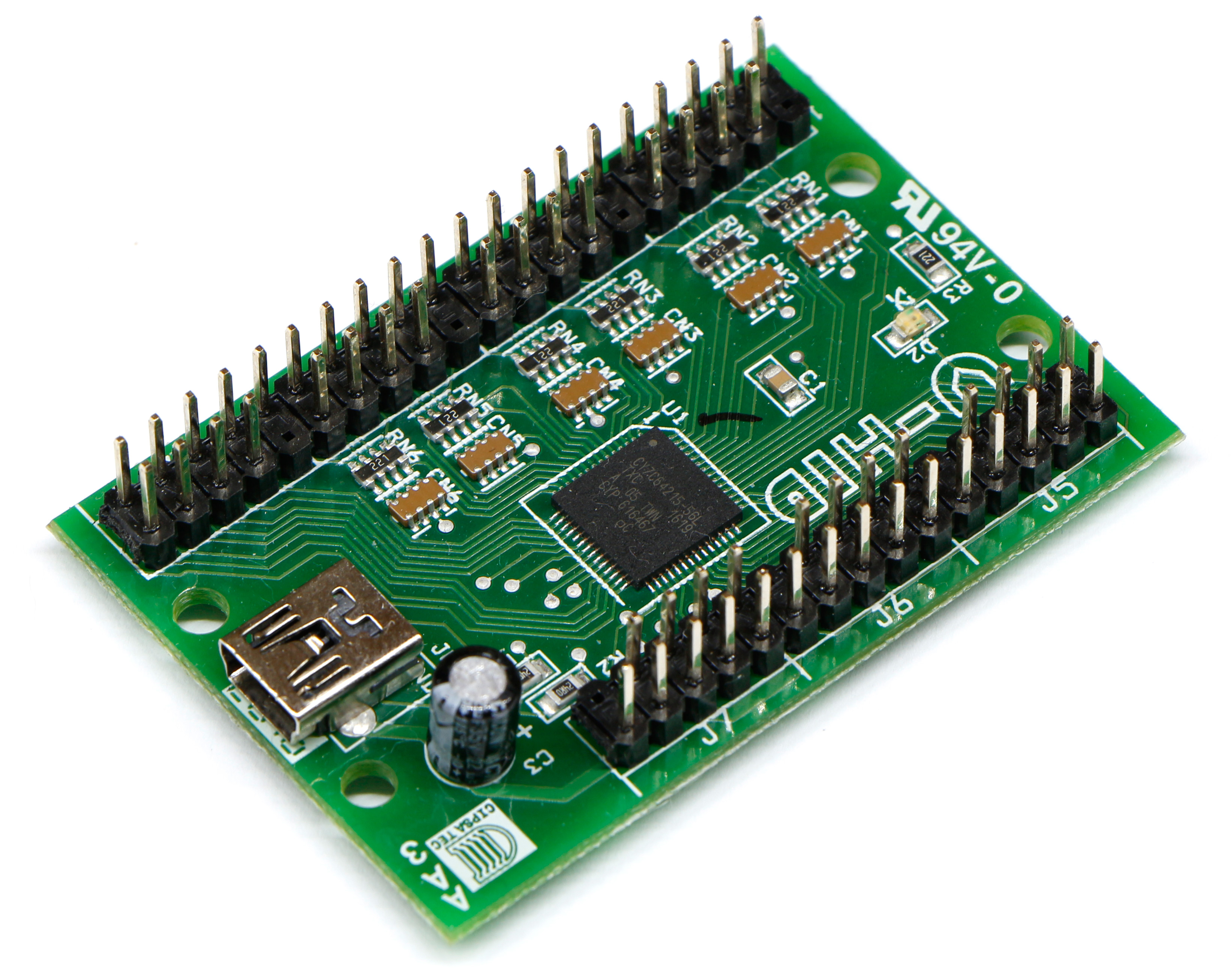


U-HID FEATURES
USB 2.0 interface
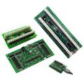
50 connections arranged in an open pin-header format allowing multiple varieties of standard connector to be used.
Connections can be assigned as:
- Keyboard key
- Gamepad Button
- Gamepad analog axis with or without auto-calibration and center dead-zone.
- Mouse button (including double-click)
- Quadrature Mouse Pair. X or Y axis. Normal or reverse direction.
- Quadrature left/right button presses.
- PC-controlled LED output using special software
- PC Num/Scroll/Caps lock LEDs
- U-HID locally-controlled LED output based on the state of any switch.
- 5 Volt output (30ma max)
- Ground
- No special drivers or application changes needed except for PC-controlled LEDs which has an API with code examples.
- Simple open pin-header connectors allow use of separate or composite modular wiring harnesses.
- U-Config configuration utility allows the connections to be configured for each device type, and keycodes and other attributes set.
- Switches handled by super-fast logic using an individual de-bounce state counter for each input giving ultimate performance for gaming applications.
- No key ghosting or blocking ever.
- Advanced keycode/button programming with in-built shift feature. Includes macro capability
- 12-bit analog axis support
- Configuration utiity interacts real-time with the board and all settings stored instantly in Flash ROM on the board.
- Single Mini-USB connector for PC (or MAC) connection. No separate power needed
- 50 Truly independent inputs allow all switches to be commoned to ground. No matrix or diodes
- Modular 8-way + ground harnesses available.
- Extended switch harnesses available.
- ESD protected inputs. Vital for high-footfall public applications.
- All settings stored in Flash ROM and retained after power-off.
- Configuration can be changed on-the-fly using a command-line. The board can assume a completely different layout instantly.
- Simple-to-use PC Configuration application.
- Up to 8 boards can be connected. All are configured using the same U-Config utility.
Advanced Features:
Key and Button functions can have one primary and one secondary code assignment.
Secondary assignments are invoked by first activating a “U-HID Shift” connection.
Any connection can be assigned as a shift.
Unique separately-programmable “button down” and “button up” events
allow use of all types of normally-closed, normally-open, or active
high/low controls.
“Button down” and “button up” can be separately assigned as primary or secondary codes.
Controls can be assigned as “normal” or “pulse”.
Toggle (push on-push off) and flip-flop modes available.
Programmable analog offset and scale factor for all analog axes.
X and Y axes can be configured with adjustable center dead-zone and auto-calibration.
Extended macro capability.
User-upgradeable firmware for future enhancements and customizations.
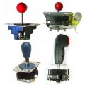
Examples of control types which can be connected:
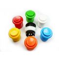
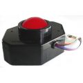
- Pushbuttons
- Switch-type joysticks
- Toggle switches
- Toggle switches with integral LED (does not require a second connection for the LED)
- Momentary pushbuttons with integral LED (LED can be controlled without any host application, or can be host-controlled)
- LEDs associated with a switch. (LED can be controlled without any host application)
- LED indicators driven by a PC application.
- Other devices can be controlled either directly or via an external high-current driver
- Analog joysticks
- Incremental Rotary encoders (Spinners).
- Low-resolution rotary encoders (360 degree volume control type)
- 12-way or N-way rotary switches used as encoders (requires simple diode circuit)
- Trackballs
- Pots
- Optical steering wheels
- Pot-type steering wheels
- Pot-type throttle pedals
- Analog Voltage sources (0-5 volts).
- TTL logic signals.
Control counts which can be configured:
Total 50 connection pins.
Max 8 analog axes on 50 possible pins (Windows limitation)
Max 32 Gamepad buttons on 50 possible pins (Windows limitation)
Max 8 Quadrature mouse devices on 16 possible pins out of the 50.
Max 3 Quadrature mouse axes (X, Y and Z, Windows limitation)
Max 50 keyboard keys on 50 possible pins.
Max 16 LEDs in any combination of PC or U-HID controlled. (USB 500 mA current limitation).
Max 50 low-current output drivers.
The
U-Config Configuration
utility

This utility is used for the following:
-
Assigning a board number (1-8) if you have multiple boards.
-
Configuring each pin of the board as the correct device type, ie keyboard, gamepad, analog, quadrature mouse, power.
-
Configuring each pin with the correct keycode, button number, axis or other parameter
-
Assigning macros
-
Configuring analog axis scale factor and offset
-
Loading and saving configurations
-
Initiating a firmware upgrade
-
Downloading a configuration "on the fly" using a command-line task
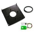
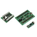
The
graphical picture of the board shows the way in which the pins are
divided into sections, each being one 9-pin connector (plus key). Pin 1
is the key and pin2 is ground.
The
utility interacts with the board in real time, every time a change is
made.
The
configuration is stored in flash ROM on the board so it remains after
power off/on.
When
the utility is run, it reads the configuration from the connected
board(s) and displays it.
You can also store the entire configuration as a file for later
downloading on-the-fly for multiple configurations.
Function of each GUI feature:
GENERAL
tab (main window)
PIN
drop down
This
displays the selected pin you
are configuring. You can select pins from here or from the main graphic.
NICKNAME
You can type text in here which will
remind you of which device this pin is connected to. The test is saved
with the configuration (on the PC only) and is not sent to the board.
FUNCTION area
Here
you configure the selected pin
as the required device type and assign values to it.You
can select one of the radio
buttons to define the pin as the following:
Switch (which includes keyboard key, gamepad button and mouse buttons)
Quadrature Mouse (includes trackballs, optical steering wheels etc)
Analog (Gamepad type control)
LED output (includes U-HID and PC Controlled)
+5 Volts out (max 30 ma)
Ground.
APPLY
This button applies the changes you
have made to the pin.
GRAPHIC
AREA
You
can click on any pin on the
graphic to start configuration of this pin. Additionally,
if you click on the pin
types listed in the center of the PCB, this will show which pins are
allowed to be configured as this type of control.You
will notice that certain pins on
P7 are fixed. These are high-current power/ground pins and are
hard-wired and cannot be changed.Each
10-pin connector area has one
hard-wired ground pin.
CALIBRATION
tab
This tab allows you to set scale factor and offset for each analog
input. The default values give a full-scale travel with the cross-hair
centered at mid-position of the pot. It may be necessary to experiment
with these settings and you can observe the result by opening Control
Panel, Game Controllers in Windows, and clicking on the came controller
device to display the calibration screen.
In addition the Calibration tab also contains the setting for
Quadrature Button press time (U-HID Only). This is the length of time
(actually the number of USB packets) which the game controller button
is pressed for when using Quadrature Buttons. This is a global setting.
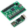
On the BlueHID board, Power Saving mode configuration is set here. Refer to the BlueHID manual for full details of power saving features.
Disconnect Timeout
The slider defines how many seconds of no-activity elapse before the board disconnects the Bluetooth link. Or you can opt to have the board never disconnect but this will consume more battery power
Wake Any Pin
button
After disconnection, the board will wake and re-connect if
activity is detected on any pin which is defined as a switch.
Wake
J2-6 Only Button
When this is selected, the board will only wake when activity is
detected on pin J2-6. In this mode (Stop Mode) the board is in maximum
power-saving state.
Self-Test LED The self-test on-board LED can be disabled. This is
recommended after testing is complete, to conserve power.
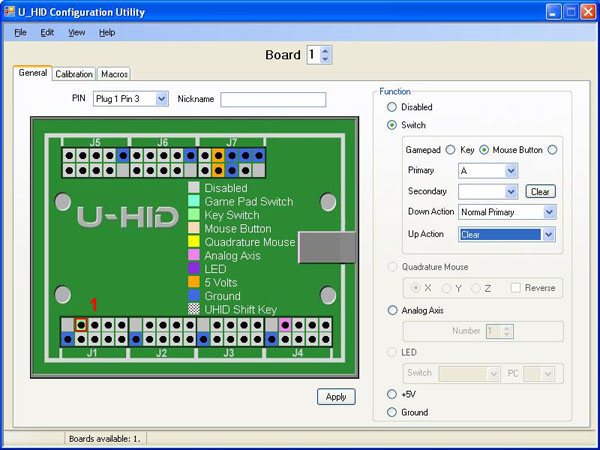
Detail Configuration Example (Switch)
The
screenshot above shows this
configuration.
We will look at how a switch is connected and configured.
Firstly, the switch is connected
with
one terminal routing to the appropriate pin and the other to a ground
pin.
Then, select the pin by clicking
on
it in the graphic area.
Select the "Switch" radio button
in
the Function area.
You now need to select what type
of
control this will be, whether a mouse button, keyboard key or gamepad
button. Lets select keyboard key.
In the Primary drop-down, all
possible keyboard keys will be available, plus macros. Macros are
defined separately, see later.
Select which keyboard key you need. Note that the U-HID sends key
scan
codes, just like a keyboard. It does not send characters so has no
concept of upper/lower case. An upper-case character is two keys (ie
shift and the character key). There is no need to assign a
secondary code unless you wish to use the shift feature or other
special functions, see later.
Then, you need to tell the board
how
and when to send the keycode you have chosen. This is done with the
Down and Up Action drop downs. These can be selected as follows:
Clear
This removes the keycode
associated with this pin from the buffer, so it is no longer sent
Normal
Primary
This sends (and holds) the
primary keycode you selected above, to the PC. If the U-HID Shift
button is pressed, it will send the secondary code instead.
Normal
Secondary
This sends (and holds) the
secondary keycode but you have not assigned one at this point so no
action.
Pulse
Primary
This sends a short pulse,
simulating the key being pressed then released, even though it might
still be physically closed (eg a toggle switch left closed)
Pulse
Secondary
This is the same as above but
pulses the secondary code.
Toggle
This is not explicitly an
option, but is the result of setting both the Down and Up actions to
Normal Primary. This will cause the selected keycode to alternately be
sent or not sent on alternate button presses.
Flip-Flop
This is not explicitly an
option but is the result of setting Down action to Secondary and Up
action to Primary. This will cause the primary or secondary key to be
sent on alternate button presses.
See-Saw
This is not explicitly an option but
is the result of setting Down action to Primary and Up action to
Secondary. This will cause the primary key to be sent on press and
secondary on release. Normal or Pulse mode can be used.
The
most common usage of keyboard keys is to set Down Action to Normal
Primary and Up Action to Clear.
Important
Note about keyboard keycodes
:
On USB keyboards (and therefore the U-HID) the auto-repeat of the
keyboard is done in Windows. So if you assign any keycode to be pressed
permanently (which can occur in many configurations) you will get an
endless string of characters in your application. For this reason, many
of the advanced combinations should only be used with gamepad buttons,
which do not have a problem being held in the pressed position.
You should also avoid
defining any keyboard keys from being "pressed" by default as this will
cause boot failures (stuck key) and may cause unexpected problems in
the Windows GUI.
Other
switch types:
Mouse
Button
You can select left, middle,
right and left double-click from the drop-down.
Gamepad
Button
These are numbered 1-32 as
shown in "Control Panel, Game Controllers".
Quadrature
Mouse Selection
This
selection always uses two pins.
When you assign the pin as this device type, the opposite pin will also
automatically be assigned.
You can select X, Y or Z (wheel)
axis.
Trackballs use two axes (4 pins).
Quadrature Button Selection
This selection uses two
pins. When you assign the pin as this
device type, the opposite pin will also automatically be assigned.
You can select one of 8 pairs of game controller buttons which will be
pressed repeatedly when the encoder is turned. Note you can configure
the "press" time on the Calibration tab.
Analog Axis
These are
numbered 1-8. You can view
analog axes using Control Panel, Game Controllers.
The first two axes are displayed as X and Y.
LED
There are two types of LED.
U-HID controlled (switch)
This type of LED is switched
on when the switch allocated to it is sending its keycode or button
(which might not necessarily mean the switch is physically closed,
depending on how the switch pin is configured).
In the drop-down, you can select which switch (referenced by its pin)
controls this LED.
PC Controlled LED
This type of LED is switched on/off by a PC application. These are numbered 1-16.
Other Functions
FILE menu
Open, Save
These selections allow loading/saving of .HID configuration files, so you can have multiple saved configurations.
Import/Export
You can import and export configurations to a CSV or XML file so you can edit them outside of the application or generate using a different application.
Assign ID
This is an important first step when you are using more than one board. You will need to connect ONE board, and assign it as number 2 or higher. Once all boards are assigned with different IDs, they can all be connected to their own USB ports. You can check which board is which by opening Control Panel, Game Controllers. The board ID# is displayed a the top of each Game Controller window.
Firmware Upgrade
This initiates a firmware upgrade. The board assumes a different USB ID and a driver will be installed. Details will be included with firmware.
VIEW menu
There is
only one option, "View U-HID Shift Option". This is normally hidden in
the main area to avoid clutter.
This is only used when assigning a pin to be a U-HID shift key.
The
shift option allocates a key (or keys) which, when held, cause other
pressed keys to send their secondary instead of primary keycodes. This
over-rides the Primary/Secondary Action defined for keys
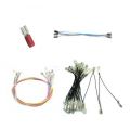
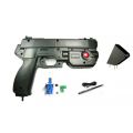
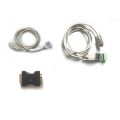
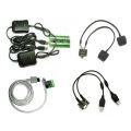
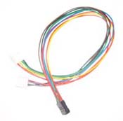
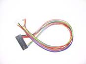
Modular 8-way Harness

This consists of 9 wires, (8 inputs plus ground) and plugs onto any of the sections of the U-HID connector. It is keyed to avoid incorrect connection.
The harness is 900mm long (39 in) and has connectors at both ends. It can be cut in half to give two open-ended wiring harnesses, then the appropriate connector fitted for the switch or other device.
Other Harnesses:

Harness Type 1
Harness for Ultimarc U-Trak Trackball. Connects to any of the U-HID connectors.
Harness Type 2
Harness for U-Trak Trackball and SpinTrak spinner. Connects to top row of pins on U-HID. Note the other connector locations can be used with harness 4
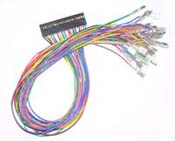
Harness Type 3
Connections for 32 switches. With 4.7 mm or 6 mm push-on female connectors. Length 350 mm
Harness Type 4.
Bundle of 10 550 mm wires with either 4.7 or 6 mm push-on female connectors. Can be used to add to harness 2, or replace wires in harness 3 for longer reach.
Device Type: Switch/Pushbutton
Any pin can be defined as a switch.
You can define a switch as:
- Mouse button (including double-click)
- Gamepad button
-
Keyboard key.
Each switch input has a primary assignment and a secondary assignment (optional).
Both the primary and secondary assignmets can be used in key action settings and the secondary assignment is also activated in place of primary when a "U-HID Shift" key is held down.
You can assign a different action for the event when the switch is closed (ie grounded) and for when the switch is opened.
The two possible keycodes (or buttons) coupled with the way in which you define closed/open events gives a mass of flexibility in the types of control you can connect without using any external circuitry.
The keycode which is sent when you activate the switch is defined
using the U-Config utility. You can assign any connection to send any
keypress.
Switches can also be assigned as game controller buttons, which are numbered 0-32 (32 is a Windows limitation).
Mouse button selections available are left, right, middle or left double-click.
Example 1
Simple keyboard-type button (Normally Open):For this you would set the “down” action to be the required keycode and “up” action to be “Clear”.
Example 2
Simple keyboard-type button (Normally Closed):Set “down” action to be “clear” and Up action to be the required keycode.
Example 3
Toggle switch with integral LED:
This type of switch sends a 5 volt signal when closed, and ground when
open. Let’s say you want to turn on a control when you switch “on” the
toggle but you don’t want to generate masses of key-presses which the
toggle is still down. You can send one key-press only, by
configuring:“down” action to be “clear” and “up” action to be “pulse”
and the required keycode. Setting it up this way means the internal LED
in the switch will function properly with no external circuitry to
control it.
Connecting Switches
Usually you would use normally-open switches or pushbuttons (although the U-HID does support normally-closed)
One connection of each switch would be connected to the required U-HID
input pin. The other to any ground pin. So, if many switches are used on
a control panel, all of them have one connection which is
"daisy-chained" to each other and routed back to a ground pin. We supply
a pre-made "daisy-chain" wiring harness which can be used for this
purpose.
ESD Protection
Connectors J1, J2 and J3 have ESD static discharge protection. These 24 pins should be used in preference over the others when connecting switches. ESD can be a problem in warm dry environments and can cause false triggering or even damage.
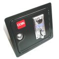
Special-Purpose Switches
Some switches have special connectivity or an in-built LED which mean you need to connect in a different way to the U-HID. The principle is always that the U-HID pin is assumed to be sitting at a voltage of 5 volts when not activated and zero when activated (but note that you can reverse the behaviour the PC sees using the config utility). If the circuit is "open" (ie a normally-closed switch is not activated) then it will sit at 5 volts.
Switches which have in-built self-powered LEDs will have a connection which sits either at zero or supply voltage. These switches would require a constant 5 volt supply to one terminal, a ground on another terminal, and the switched voltage appears on a third. The switched voltage is connected to the U-HID input pin. These switches actively tie the pin to 5 volts (supply) or ground. This is fine for the U-HID.
Important! Never connect any device to the U-HID which sends more than 5 volts otherwise damage could occur!
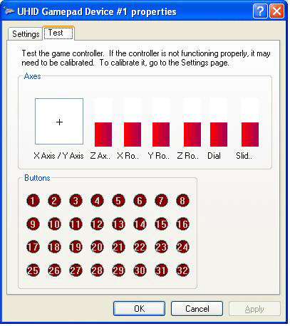
Testing Switches
Switches defined as keyboard keys can be tested using Notepad or any program which displays text.
Gamepad buttons can be tested using Control Panel, Game Controllers. The display is shown below:
Device Type: Switch/Pushbutton
Any pin can be defined as a switch.
You can define a switch as:
- Mouse button (including double-click)
- Gamepad button
-
Keyboard key.
Each switch input has a primary assignment and a secondary assignment (optional).
Both the primary and secondary assignmets can be used in key action settings and the secondary assignment is also activated in place of primary when a "U-HID Shift" key is held down.
You can assign a different action for the event when the switch is closed (ie grounded) and for when the switch is opened.
The two possible keycodes (or buttons) coupled with the way in which you define closed/open events gives a mass of flexibility in the types of control you can connect without using any external circuitry.
The keycode which is sent when you activate the switch is defined
using the U-Config utility. You can assign any connection to send any
keypress.
Switches can also be assigned as game controller buttons, which are numbered 0-32 (32 is a Windows limitation).
Mouse button selections available are left, right, middle or left double-click.
Example 1
Simple keyboard-type button (Normally Open):For this you would set the “down” action to be the required keycode and “up” action to be “Clear”.
Example 2
Simple keyboard-type button (Normally Closed):Set “down” action to be “clear” and Up action to be the required keycode.
Example 3
Toggle switch with integral LED:
This type of switch sends a 5 volt signal when closed, and ground when
open. Let’s say you want to turn on a control when you switch “on” the
toggle but you don’t want to generate masses of key-presses which the
toggle is still down. You can send one key-press only, by
configuring:“down” action to be “clear” and “up” action to be “pulse”
and the required keycode. Setting it up this way means the internal LED
in the switch will function properly with no external circuitry to
control it.
Connecting Switches
Usually you would use normally-open switches or pushbuttons (although the U-HID does support normally-closed)
One connection of each switch would be connected to the required U-HID
input pin. The other to any ground pin. So, if many switches are used on
a control panel, all of them have one connection which is
"daisy-chained" to each other and routed back to a ground pin. We supply
a pre-made "daisy-chain" wiring harness which can be used for this
purpose.
ESD Protection
Connectors J1, J2 and J3 have ESD static discharge protection. These 24 pins should be used in preference over the others when connecting switches. ESD can be a problem in warm dry environments and can cause false triggering or even damage.
Special-Purpose Switches
Some switches have special connectivity or an in-built LED which mean you need to connect in a different way to the U-HID. The principle is always that the U-HID pin is assumed to be sitting at a voltage of 5 volts when not activated and zero when activated (but note that you can reverse the behaviour the PC sees using the config utility). If the circuit is "open" (ie a normally-closed switch is not activated) then it will sit at 5 volts.
Switches which have in-built self-powered LEDs will have a connection which sits either at zero or supply voltage. These switches would require a constant 5 volt supply to one terminal, a ground on another terminal, and the switched voltage appears on a third. The switched voltage is connected to the U-HID input pin. These switches actively tie the pin to 5 volts (supply) or ground. This is fine for the U-HID.
Important! Never connect any device to the U-HID which sends more than 5 volts otherwise damage could occur!
Testing Switches
Switches defined as keyboard keys can be tested using Notepad or any program which displays text.
Gamepad buttons can be tested using Control Panel, Game Controllers. The display is shown below:
|
Device Type: Switch/Pushbutton Any pin can be defined as a switch. You can define a switch as:
The keycode which is sent when you activate the switch is defined
using the U-Config utility. You can assign any connection to send any
keypress.
Example 1Simple keyboard-type button (Normally Open):For this you would set the “down” action to be the required keycode and “up” action to be “Clear”. Example 2Simple keyboard-type button (Normally Closed):Set “down” action to be “clear” and Up action to be the required keycode. Example 3Toggle switch with integral LED: Connecting SwitchesUsually you would use normally-open switches or pushbuttons (although the U-HID does support normally-closed) ESD ProtectionConnectors J1, J2 and J3 have ESD static discharge protection. These 24 pins should be used in preference over the others when connecting switches. ESD can be a problem in warm dry environments and can cause false triggering or even damage. Special-Purpose SwitchesSome switches have special connectivity or an in-built LED which mean you need to connect in a different way to the U-HID. The principle is always that the U-HID pin is assumed to be sitting at a voltage of 5 volts when not activated and zero when activated (but note that you can reverse the behaviour the PC sees using the config utility). If the circuit is "open" (ie a normally-closed switch is not activated) then it will sit at 5 volts. Switches which have in-built self-powered LEDs will have a connection which sits either at zero or supply voltage. These switches would require a constant 5 volt supply to one terminal, a ground on another terminal, and the switched voltage appears on a third. The switched voltage is connected to the U-HID input pin. These switches actively tie the pin to 5 volts (supply) or ground. This is fine for the U-HID. Important! Never connect any device to the U-HID which sends more than 5 volts otherwise damage could occur!Testing SwitchesSwitches defined as keyboard keys can be tested using Notepad or any program which displays text. |
![]()
Device Type: Analog Input
A pin assigned to Analog senses a voltage on the pin and controls a gamepad X, Y, or other axis on the PC.
Analog resolution is 12 bit.
The voltage can vary between 0 and 5 volts.
Usually this voltage will come from a potentiometer (pot) which is part
of a steering wheel, handwheel, throttle pedal, or other type of analog
control.
You can assign any pin to one of 8 possible analog axes. (8 is a Windows limitation).
To test, go into “Control Panel”, “Game Controllers”. Then select the board number (if you have more than one board).You will see the X, Y crosshair (axes 1 and 2 on the U-HID board) and also the other 6 axes as red bars.
Offset and Scale
In the U-Config program, on the second page of the GUI, you can
select an offset. This is a fixed displacement of the control. Usually
this is set in the center, giving a conventional joystick type of
control.
Also, you can set a scale factor, which defines the sensitivity of the control.
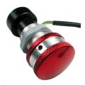
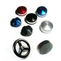
Device Type: Optical or Mechanical Encoders
High-resolution Quadrature devices usually consist of a pair of optical sensors and an encoder wheel. Examples of such devices are:
- Spinners such as the Ultimarc SpinTrak
- Trackballs such as the Ultimarc U-Trak
- Incremental Optical Rotary Encoders
- Incremental Mechanical Encoder eg ALPS EC12 Series
- 12-way rotary switches such as the Happ Controls Rotary Joystick. See App Note AN1001
- Linear Motion Sensors
|

|

|
| ALPS EC12 Mechanical | Ultimarc U-Trak | Ultimarc SpinTrak |
Quadrature devices can be used in two ways. They can be used to control the mouse pointer in an X, Y or Z direction, or they can be used to repeatedly pulse gamepad buttons. In general, mouse mode is used for high-resolution optical encoders and button mode for low-res mechanical but there may be applications where the opposite mode is useful.
Quadrature devices use two input pins per device, and optical devices will require GND and 5V pins. Mechanical encoders require GND only, and this is the center pin on 3-pin devices.
Windows allows one instance of each axis when defined as Mouse (ie X, Y, Z) but if you are using multiple U-HID boards, Windows can recognise each board as a different mouse, using DirectInput.
Devices should be capable of operating with a 5 volt supply (not required for mechanical encoders).
This can be obtained either by configuring a pin as 5V or using one of the fixed 5V sources on connector J7
They also require ground, which can be connected to a configured pin or one of the ground pins on each modular connector.
Note that only certain pins can be configured for quadrature devices. These can be seen in U-Config by clicking on the "Quadrature" line in the PCB image. Appropriate pins will be highlighted. Two pins are used per device. An X-Y device such as a trackball counts as two devices and therefore uses 4 pins.
Mouse Mode
Encoders configured in this more simply move the mouse pointer in the X, Y or Z direction. Note the Z axis in Windows performs differently to X and Y. It accepts a fixed displacement per data packet rather than a variable one. This means the Z axis might not be suitable for many applications as it is very sensitive when using a high-res encoder.
Button Pulse Mode.
In this mode, the quadrature device is assigned to a pair of Game
Controller buttons. The pairs are buttons 1,2, buttons 3,4 etc up to
15,16.
When the encoder is turned in one direction, the first button will be
repeatedly "pressed". When turned in the other direction, the other
button of the pair will be repeatedly "pressed".
The press time is configurable. This is a global setting on the
"Calibration" page of U-Config. The setting here can be set from 2 to
32. The figure is actually the number of USB data packets sent for each
press. Between each press, there must of course be a "release" period
and this is the same time as the press.
It might be necessary to experiment with this setting as there is a
trade-off. Too fast a setting will cause presses to be missed by the
application, and too slow will cause slow response of the control.
When this mode is used for high-resolution encoders, the buttons will be
pulsed at the maximum configured speed which is much higher than the
real pulse-rate from the encoder.
Example1
Assume you have a pushbutton which has an internal LED. It is a
momentary button so cannot be used to directly switch the LED since it
would only light while the button is pressed.
You have this button configured as a toggle (push on, push off).
You can assign the LED to this button, and it will light when the button
is pressed and go dark when it is pushed again, in sync with the
buttons action in the application.
Example 2
Assume you have a toggle switch which grounds one connection when closed. This could not be used on its own to also control a LED.You could link a U-HID controlled LED to this connection and it would light while the switch s closed.
Up to 16 connections can be assigned as U-HID-controlled LEDs. When
you assign these LEDs, you link it to any other connection. The other
connection must be defined as a switch. This other connection will
control the state of the LED.
Its important to realize that the LED state is not actually controlled
by the other switch connection pin directly, but by the boards stored
internal state of the control connected to that pin. This means the
control of the LED is affected by how the switch is defined as well as
its actual open/closed state.
The limit of 16 LEDs applies to the board to stay within USB specificatons on current draw (500mA). The U-Config utility will allow you to configure more than this but a LED count on the status line will show red as a warning. You can configure more than 16 if you are using the outputs as low-current drivers, eg for TTL signals.
The U-HID will drive standard LEDs only.
Pins on J1, J2 and J3 have integral resistors so you can directly connect standard LEDs to these. Other pins will need a series 220R resistor, or use 5 volt LEDs with an in-built resistor.
LEDs are connected between the U-HID pin and ground.
The pre-made modular harness can be used to connect LEDs.
Up to 16 connections can be defined as PC-Controlled LEDs. You can also use these for other output functions.
These LEDs are controlled by a software application on the PC. There are sample APIs for developing your own applications to add LED control.
You can also assign LEDs to behave as keyboard CAPS, NUM and SCROLL
lock LEDs. They will be turned off or on in the same way as your regular
keyboard LEDs.
Maximum current draw is 30mA per pin.
The limit of 16 LEDs applies to the board to stay within USB
specificatons on current draw (500mA). The U-Config utility will allow
you to configure more than this but a LED count on the status line will
show red as a warning. You can configure more than 16 if you are using
the outputs as low-current drivers, eg for TTL signals.
The U-HID will drive standard LEDs only.
Pins on J1, J2 and J3 have integral resistors so you can directly
connect standard LEDs to these. Other pins will need a series 220R
resistor, or use 5 volt LEDs with an in-built resistor.
LEDs are connected between the U-HID pin and ground.
The pre-made modular harness can be used to connect LEDs.
 LED control for advanced users.
You can assign any connection as power output (+5V) or ground.
You need to be aware of the following limitations:
- Power and ground pins can only source/sink 30mA max current per pin.
- Total current draw must not exceed 500mA
If you need more current than 30mA then you can use one of the fixed
power pins on connector J7. See the U-Config program board image for
details of which pins these are. In fact it is good practice to use
these pins whenever possible for a 5 volt source as they are powered
directly from the USB supply.
Using assigned pins instead offers advantages of modular connectors and
is particularly useful for optical devices which always need a supply
for the optical switches and dont have a large current requirement. As
each modular plug has one fixed ground connection you would rarely need
to assign a ground pin.
The internal shift feature allows you to define a connection (or connections) which when activated, cause all other switch connections to send an alternate command.
This is rather like a keyboard shift key which, when held, causes the keyboard keys to send different characters. When the internal shift connection is activated and held, the Secondary function of all other keys is sent instead of the Primary.
EXAMPLE 1:
In a gaming controller you might wish to assign an admin function such as COIN INSERT and you don’t wish to have a dedicated button on the panel for this. You could make PLAYER1 START an internal shift connection. Then assign a secondary COIN INSERT function to the switch which is normally “PLAYER 1 FIRE”. So to insert a coin, hold PLAYER1 START and press PLAYER1 FIRE.
EXAMPLE 2:
You have a control panel which is used for two completely different functions and you wish these functions to be selectable using a toggle switch. You could assign a spare connection as an internal shift connection, and then connect a toggle switch to it. Then assign all Primary functions to your first control panel type and all Secondary functions to the second type. Switching the toggle would flip the panel from one mode to the other. (Be aware you can also achieve this by re-programming the board on-the-fly though!).
Defining Internal Shift Connections
Normally you would perform this on only one connection, which will act as the shift key.
Most users would only require to define this function once, so to avoid clutter on the display, it is hidden unless the connection is completely un-assigned. This means with the default configuration, which has all connections assigned, you won’t see this option.
To assign a connection as an internal shift:
Click on the connection and select “not used”. A check box will appear with the option “This is an Internal Shift Switch”.
Enable the check box. This will be highlighted in red and will remain visible while this connection is selected.
Checking this box limits what you can do with the other selections for this switch. You are limited to assigning a “Pulse action on Open” , or no action at all. Any other type of assignment is invalid for an internal shift connection.
You cannot assign this connection as an LED, Analog or Quadrature input.The ability to assign a “pulse on open” action means you can also have this connection perform its own function as well as being a shift key.
If the key is pressed and released, it will send its own function as a pulse, provided no other connection has been activated in the meantime. This is how Example 1 works, above. The Player 1 Start function of this key still works even though it’s a shift key as well. You can assign any number of the connections to be internal shift, but they all will enable the same shift functionality in addition to their own individual assigned code (if any).
U-HID Self-Test LED
The On-board Self-Test LED is connected to J6 pin 5.
In normal operation, the LED will illuminate when:
- The device is in the process of enumerating with the USB host controller during boot or plugin
- The device is receiving configuration data from the host
- A switch connected to this pin is closed.
In addition, you can use this LED for test purposes by defining J6 pin 5 as a LED. NOTE: The LED is connected between the pin and 5V power on the PCB. This means it will behave in an opposite way to other connected LEDs which are connected between the pins and Ground.
Connecting analog devices such as pots to this pin wil give strange results but you can use the LED for a basic pot test (brightness will vary).
BlueHID Self-Test LED
The self-test LED can be enabled and disabled from within the U-Config utility and should be disabled after installation and testing is complete.
If enabled:
Board powered up: LED flashes once
Board connected via Bluetooth: LED lights
Board goes to bound authorised state: LED goes off
If enabled the LED also blinks at the rate of data polling by the host system This means during normal operation it is seen to be lit constantly, then in idle mode progressively blinks more slowly. This can be used to check that no external device or connection is preventing power saving modes from being invoked. The LED is connected on the board to J1 pin 4. It can be controlled from the host if require
Full U-HID Technical Manual: Click to download
Full BlueHID Technical Manual: Click to download
U-Config
Updated Jan 2016: Now also supports BlueHID board.
The U-Config application can be downloaded here:
Output Driver SDK
The SDK is shared with other Ultimarc products and can be found on the "SDK Programmers Page" tab.
ULTIMARC PROGRAMMERS PAGE
This page contains details of software available for all products for controlling output devices, reading inputs programatically and other usage.
Output control:
- PacLED64
- PacDrive
- U-HID PC Controlled LEDs
- I-PAC Ultimarc I/O Controlled LEDs
- NanoLED
- USBButton
- Servostik 4-8 way switching
Input:
- USBButton Read State
Demo Code:
- PACDriveDEMO with source. Covers all products above and includes a GUI control panel
Linux Library and command line utilities developed by Katie Snow
The Ultrastik360 is accessible via DirectX/DirectInput, an unmanaged C/C++ programming interface. Using this interface in .NET requires knowledge of C++ by writing managed wrappers. The open source library from http://sharpdx.org/ did exactly that, so using the stick in .NET is now done in a few lines of code.
This Example shows a simple example in C#. The minimum needed parts of the SharpDx library (2 dll’s, 700kb) are automatically downloaded and managed via NuGet when you compile first time.
- SetupTestSharpDx.exe file is a full automatic inno-setup which places the required binaries in ‘program files’ (exe with some dlls)
- The binaries file contains the same files, but without setup. Unzip them anywhere
- The source file contains a readme, the visual studio 2013 C# project with all necessary source files (Framework 4.5.1).
All our firmware-upgradeable USB products use the same method for upgrade.
This is how it should work:
- Firmware upgrade requested from the appropriate utility (WinIPAC, Ultramap, U-Config etc) The utility must be right-clicked and "run as administrator".
- A driver is pre-installed automatically. This is the only time any of our products require a custom driver.
- The device is shut down by the utility and then resets as a different device, which is known as a "Firmware Upgrade Device".
- This new device should appear in Device Manager, if the "USB Controllers" entry is expanded.
- A program called "uupload.exe" is started automatically by the utility. The utility is then closed down.
- The "uupload.exe" window should appear and a "device detected" message should appear.
- The firmware file is selected from this window and upgrade should proceed. Do not be concerned if the progress bar does not show.
- The upgrade should take max 5 minutes. After that, the device is reset back into normal operation mode, and at this point the uupload program can no longer see it, and should display "No device detected or upgrade complete".
Uupload.exe cant find the upgrade device
The most common reason for this is the custom driver install has failed. This can be checked by starting device manager and expanding the "USB Controller" entry. The device might be showing with an error, or there might ne a new device somewhere else in Device Manager which has failed to install.
The fix for this is as follows:
- Download the manually-installed driver from the link in the section below and run "setup" located in the setup folder. NOTE: Must be right-clicked and "run as administrator".
- Right click on the failed device and "uninstall"
- Click "Scan for new hardware". The driver should install.
- Re-run the "uupload.exe" program which is located in the install folder of WinIPAC, UltraMap, U-Config etc, and re-try the upgrade.
Firmware upgrade locks up or fails to finish, resulting in stuck in upgrade mode
Simply re-run the "uupload.exe" program which is located in the install folder of WinIPAC, UltraMap, U-Config etc, and re-try the upgrade.
The various utility programs for our devices incorporate a firmware upgrade feature. This requires a driver (the only time a driver is required). The driver installs on the fly but should a manual install be required, this installer does this. Run the Setup program in the Setup folder.