- View all variations as list
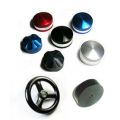
| Part Number | Handle Type | Availability | Price | ||
|---|---|---|---|---|---|
|
|
CSS01REDBL
|
|
$39.00 | ||
|
|
CSS01BLKBL
|
|
$39.00 | ||
|
|
CSS01REDOV
|
In stock
|
$39.00 | ||
|
|
CSS01BLKOV
|
|
$39.00 |

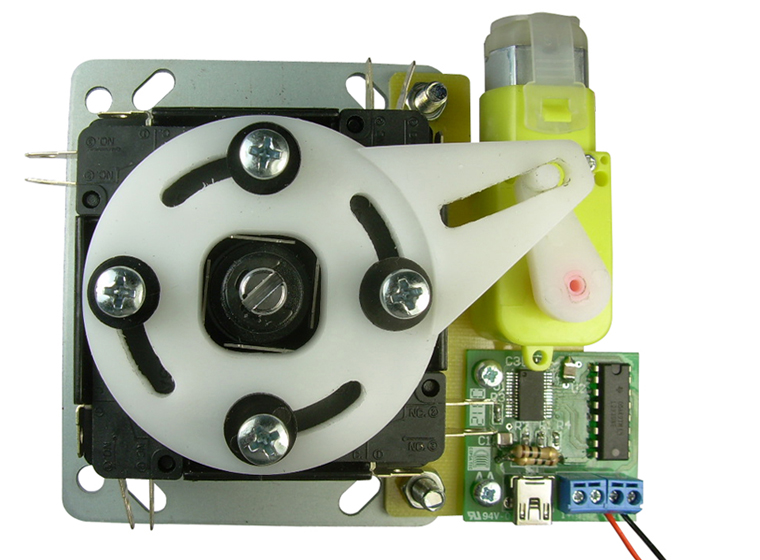
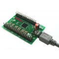
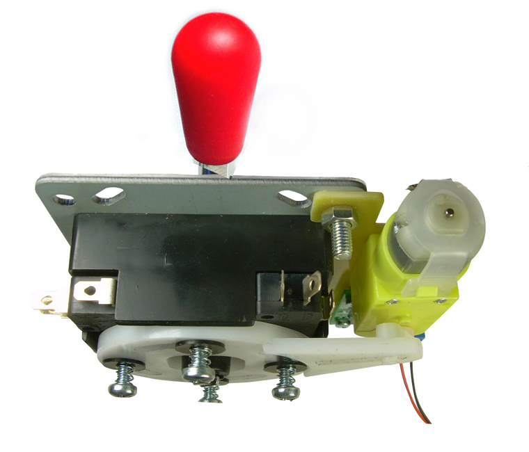
USB Servo Control board drives two joystick servos.
Can also be switched in a standalone setup (no PC) using two buttons or a toggle switch
Multiple control boards can be used on one PC for 4 or more players
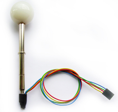
Optional RGB Illuminated handle available.
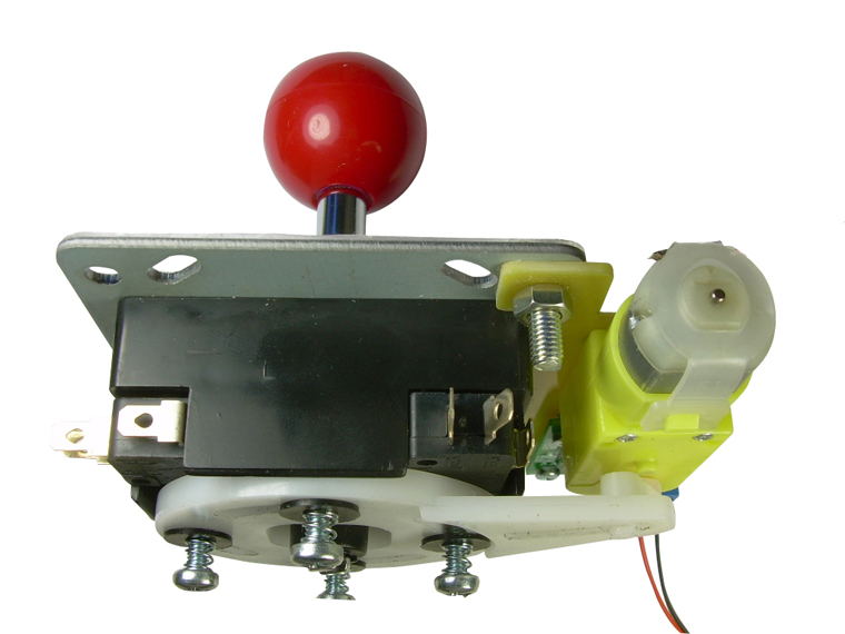
Note: Above pictures show 2 x joystick mounting screws which are not included. We have separate mounting kits available for wood panels.
Check out Daniel Spies video demo here
- At last! Full mechanical 4-8 way restriction with powered switching.
- Separate control board plugs into a USB port and controls the servos on two joysticks.
- Comprehensive software support including test utility and a special utility which can be command-line or GUI driven.
- Integrated into the Ultimarc DLL which provides API calls to perform switching, for front-end developers.
- No separate power required. Takes power from USB port
- Hardware mode also allows switching using two buttons or a toggle switch.
- Switches are connected in the same way as a standard joystick, to a suitable interface such as an I-PAC.
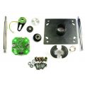
The ServoStik consists of three parts:
Base Joystick:
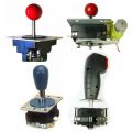
This is installed and wired to an interface in the same way as any standard arcade stick. Mounting method depends on panel design, material and thickness. Our blind-hole mounting kits can be used on wood panels of thickness 5/8 in or greater.
Motor:
The motor baseplate mounts using two of the same mounting screws as the base joystick. NOTE; The two screws shown in the pictures above, which secure the motor baseplate to the joystick are NOT INCLUDED as these are part of the joystick mounting hardware.
Control Board (Ordered separately)
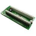
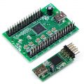
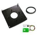
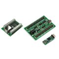
The control board can be mounted to the motor baseplate of one of the two sticks using supplied mounting hardware. Wires from each motor need to be connected to the screw terminals. One control board drives two motors. A four-player panel will require two control boards.
Test Application
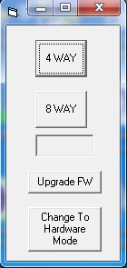
This simple application can be downloaded here.
It simply has two GUI buttons for switching to 4-way or 8-way. All detected control boards (and therefore pairs of sticks) are switched.
The app is also used for PERMANENTLY switching to hardware mode (see below).
JoyTray

This application can be downloaded here: It supports both the ServoStik and our Ultrastik 360
Running JoyTray from command line:
JoyTray.exe -servo [joy4way|joy8way]
(If using Ultrastik 360: JoyTray.exe -u360 [mouse|analog|joy8way|easyjoy8way|joy4way|djoy4way|rdjoy4way|joy2way|vjoy2way])
If you add an -exit argument the program will exit without staying resident.
Until front-end developers add native support for the ServoStik, this is the way to automate switching. The front-end needs to be configured to run a command line before starting games eg:
JoyTray.exe -servo joy8way before all 8-way games
JoyTray.exe -servo joy4way before all 4-way games
JoyTray Hotkeys:
When resident: F4 switches to 4-way and F8 switches to 8-way. You could assign I-PAC-connected controls to these keycodes. Maybe use I-PAC shifted codes.
JoyTray GUI Mode:
Launch JoyTray.exe by itself and it will show an icon in the tray which can be right-clicked to show a menu. It will gray out the U360 or ServoStik menu items based on whether you have them attached. There is an option to run the program at startup.
As most third-party software and our SDK is cross-product, we have placed all details on the SDK Programmer's Page tab.
This special mode is used when there is no PC and you need to switch the stick using a toggle switch or two buttons.
The control board can be placed into hardware mode using the test application (see above). Note this change is PERMANENT.
Switching between 4 and 8 way is done using either two buttons or a toggle switch.
To connect the buttons, cut the A plug from the USB cable and strip the wires.
Connect the RED wire to a 5 volt source. (JAMMA power supply for example)
Connect the BLACK wire to Ground on the power supply
Connect the Green wire to the NO contact of a pushbutton for 4 way
Connect the White wire to the NO contact of a pushbutton for 8 way
Connect the COM connections of both buttons to the black daisy-chain wire which runs to all other controls, or to the power supply ground.
Alternatively you can use a toggle switch with the center connection to ground and the end connections to the green and white wires.
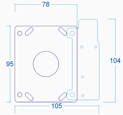
Dimensions in mm
![]()
ULTIMARC PROGRAMMERS PAGE
This page contains details of software available for all products for controlling output devices, reading inputs programatically and other usage.
Output control:
- PacLED64
- PacDrive
- U-HID PC Controlled LEDs
- I-PAC Ultimarc I/O Controlled LEDs
- NanoLED
- USBButton
- Servostik 4-8 way switching
Input:
- USBButton Read State
Demo Code:
- PACDriveDEMO with source. Covers all products above and includes a GUI control panel
Linux Library and command line utilities developed by Katie Snow
The Ultrastik360 is accessible via DirectX/DirectInput, an unmanaged C/C++ programming interface. Using this interface in .NET requires knowledge of C++ by writing managed wrappers. The open source library from http://sharpdx.org/ did exactly that, so using the stick in .NET is now done in a few lines of code.
This Example shows a simple example in C#. The minimum needed parts of the SharpDx library (2 dll’s, 700kb) are automatically downloaded and managed via NuGet when you compile first time.
- SetupTestSharpDx.exe file is a full automatic inno-setup which places the required binaries in ‘program files’ (exe with some dlls)
- The binaries file contains the same files, but without setup. Unzip them anywhere
- The source file contains a readme, the visual studio 2013 C# project with all necessary source files (Framework 4.5.1).
All our firmware-upgradeable USB products use the same method for upgrade.
This is how it should work:
- Firmware upgrade requested from the appropriate utility (WinIPAC, Ultramap, U-Config etc) The utility must be right-clicked and "run as administrator".
- A driver is pre-installed automatically. This is the only time any of our products require a custom driver.
- The device is shut down by the utility and then resets as a different device, which is known as a "Firmware Upgrade Device".
- This new device should appear in Device Manager, if the "USB Controllers" entry is expanded.
- A program called "uupload.exe" is started automatically by the utility. The utility is then closed down.
- The "uupload.exe" window should appear and a "device detected" message should appear.
- The firmware file is selected from this window and upgrade should proceed. Do not be concerned if the progress bar does not show.
- The upgrade should take max 5 minutes. After that, the device is reset back into normal operation mode, and at this point the uupload program can no longer see it, and should display "No device detected or upgrade complete".
Uupload.exe cant find the upgrade device
The most common reason for this is the custom driver install has failed. This can be checked by starting device manager and expanding the "USB Controller" entry. The device might be showing with an error, or there might ne a new device somewhere else in Device Manager which has failed to install.
The fix for this is as follows:
- Download the manually-installed driver from the link in the section below and run "setup" located in the setup folder. NOTE: Must be right-clicked and "run as administrator".
- Right click on the failed device and "uninstall"
- Click "Scan for new hardware". The driver should install.
- Re-run the "uupload.exe" program which is located in the install folder of WinIPAC, UltraMap, U-Config etc, and re-try the upgrade.
Firmware upgrade locks up or fails to finish, resulting in stuck in upgrade mode
Simply re-run the "uupload.exe" program which is located in the install folder of WinIPAC, UltraMap, U-Config etc, and re-try the upgrade.
The various utility programs for our devices incorporate a firmware upgrade feature. This requires a driver (the only time a driver is required). The driver installs on the fly but should a manual install be required, this installer does this. Run the Setup program in the Setup folder.

