


Mini-PAC Opti

- View all variations as list
| Part Number | Harness Type | Availability | Price | ||
|---|---|---|---|---|---|
|
|
PMINI+L2+L3B+L5B+LU02
|
403 item(s)
|
$69.00 | ||
|
|
PMINI+L2+L3C+L5B+L5C+LU02
|
257 item(s)
|
$69.00 |
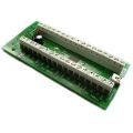
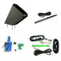
Integrated Switch/Joystick/Trackball/Spinner Interface with Wiring Harness
No
more cutting/stripping/crimping!
Do you regularly build control panels? Even if you have only built one
panel, you will know that the novelty of cutting and stripping wires,
crimping and connecting very quickly wears off! After all, on a
standard panel there are 88 wires to be stripped and 44 crimps! Why not
get someone else to do all that and use the time saved for less boring
pursuits (such as playing games!). Also, would it not be nice if this
could be done for less extra cost than buying all the wire and crimps?
Plus, how about connecting a trackball and a spinner as well, all
routed through one board and one cable to the PC, with everything
simply a plug-in connection?
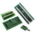
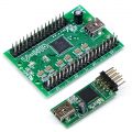
The Mini-PAC is a revolutionary combined Switch/Trackball/Spinner
Interface with wiring harness. It is designed so that a complete
control panel can be wired up in minutes. Ideal for OEM builders of
controllers and cabinets but also suitable for the first-time builder
.
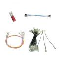
Harness Power!
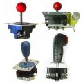
The wiring harnesses are available for 32
switches (including joysticks and buttons) and with connection for
Ultimarc trackballs and spinners. Along
with each switch harness is a "daisy chain" ground harness. The total
number of individual sections of wire on these harnesses is over 74,
with over 144 terminations! Compare the cost of the wire and
connectors, plus time saved, with the amazingly low prices of these
premade harnesses!
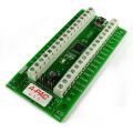
The ground harness has 4 extra terminations, so that if necessary you
can span longer distances between switches by "missing out" one
connector. Switch connectors are female with option of 0.25
inch (6.3mm) or 4.7mm. These are designed for standard
microswitch terminals.

Switch Harness
Panel Sizes
Each switch wire on the harness is 13 inches long (330mm). The Mini-PAC
board should be mounted near the center of the panel, giving a span
between the furthest switches of 26 inches (660mm). The harnesses are
designed to cover almost all standard size 2-player panels but
extension kits are available for longer distances. Ground
harness "hops" are 5 inches each.
If you are building a 4-player panel you can double up on Mini-PACs and
harnesses.
Making your own?
You can make your own wiring harness if you prefer, because the
Mini-PAC uses a standard 40-way 0.1 inch pitch pin header which can
connect to a standard IDE disk drive cable, so you can use this
inexpensive type of cable as the basis of your wiring.
Switch/Joystick Functionality
The Mini-PAC works identically to I-PAC2 board. All programming
features identical, same number of inputs (32). Works in PS/2 or USB
mode. For PS/2, you will need the optional PS/2 adaptor.
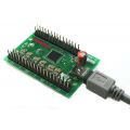
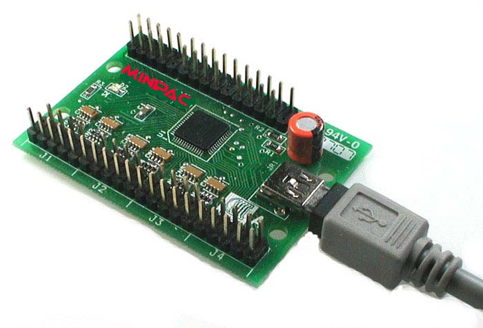
- Tiny board! Only 2 1/4 X 1 1/2 inches!
- Fully programmable key code set. Stored even after power off unlike some other interfaces which lose all data when powered off.
- Dual interface. Full Speed USB or Keyboard - small adaptor plug available for PS/2 mode.
- Lead plugs into keyboard socket on PC (with adaptor) or direct to USB port.
- Can be programmed using special utilities (for DOS, Windows, Linux, MAC)
- Using host software, an unlimited number of keycode configurations can be stored and downloaded on-the-fly. Retained on power off.
- No separate power needed.
- Does not use a matrix - no ghost keys.
- Does not use a scanning method which causes a variable delay. Each input has it's own dedicated connection into the on-board CPU .
- Fast running gives much better response than a standard keyboard controller. Key transmission and debounce uses a state method for each key. No delays between keys depressed at the same time. (essential for fighting games). No need for a keycode buffer.
- 2 modes. Either uses standard MAME keys (default) or you can program your own character set.
- Shift functions. Holding "Start1" and pressing other buttons sends a range of codes for MAME functions such as "escape", "Coin 1", "tab", "enter". This means no extra buttons are needed on the cabinet. In programmable mode any input can be the shift key and all keys can be programmed with a shifted code.
- Connector for ordinary keyboard which can be used together with the controls if required. No switch-over delays mean you could even play a game using the control panel and keyboard at the same time. Advanced interrupt-driven code means the pass-through uses NO CPU cycles when the keyboard is idle.
- Supports selective up/down key repeat in PS/2 mode (all keys repeat in USB mode) to give easy scrolling through lists with minimal CPU overhead and interface "clutter".
- No special drivers needed. USB drivers are generic Windows.
- Fully compatible with all Apple Macs which have USB ports.
- Supports the Apple Mac "command" key and the Windows "GUI" keys.
- Can be paired in any combination to increase the total number of inputs.
- Keycode programming is integrated directly into many popular MAME front end for seamless launch of emulator or other applications which require different codesets.
- Self-test LED indicator which shows and wiring or other
problems.
Trackball/Spinner Functionality
In USB mode only. No extra PC connections are needed, all
communications go through one USB cable. Inputs for one 2-axis device
(trackball) and one single-axis device (spinner).

Trackball/Spinner Harness
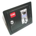
Important Legal Note.
For legal reasons we must state here that the Mini-PAC is not designed to be used in revenue-earning applications where a credit mechanism is used. The Mini-PAC contains no specific interface functionality for any credit device. Although it has inputs labelled "COIN", these are labelled as such because activating a switch connected to them causes the MAME "coin" keycodes (5 or 6) to be sent. These are designed to be used with panel pushbuttons not coin doors or note acceptors.
| INPUT | KEYBOARD MODE | KEYBOARD MODE WITH SHIFT
(hold 1 player start) |
GAMEPAD MODE |
|---|---|---|---|
| COIN 1 | 5 | BUTTON 7 | |
| COIN 2 | 6 | BUTTON 7 | |
| START 1 | 1 | BUTTON 8 | |
| START 2 | 2 | ESC | BUTTON 8 |
| 1 RIGHT | R arrow | Tab | DPAD RIGHT |
| 1 LEFT | L arrow | Enter | DPAD LEFT |
| 1 UP | U arrow | Key Below ESC (Volume, gamma, etc ) | DPAD UP |
| 1 DOWN | D arrow | P (pause) | DPAD DOWN |
| 1 SW 1 | L-ctrl | 5 (Coin A) | BUTTON 1 |
| 1 SW 2 | L-alt | |
BUTTON 2 |
| 1 SW 3 | space | |
BUTTON 3 |
| 1 SW 4 | L-shift | |
BUTTON 4 |
| 1 SW 5 | Z | |
BUTTON 5 |
| 1 SW 6 | X | |
BUTTON 6 |
| 1 SW 7 | C | |
Z LEFT / LEFT TRIG |
| 1 SW 8 | V | |
Z RIGHT / RIGHT TRIG |
| 1 A | P | HOME (xin only) | |
| 1 B | ENTER | BACK (xin only) | |
| 2 RIGHT | G | |
DPAD RIGHT |
| 2 LEFT | D | |
DPAD LEFT |
| 2 UP | R | |
DPAD UP |
| 2 DOWN | F | |
DPAD DOWN |
| 2 SW 1 | A | |
BUTTON 1 |
| 2 SW 2 | S | |
BUTTON 2 |
| 2 SW 3 | Q | |
BUTTON 3 |
| 2 SW 4 | W | |
BUTTON 4 |
| 2 SW 5 | I | |
BUTTON 5 |
| 2 SW 6 | K | |
BUTTON 6 |
| 2 SW 7 | J | Z LEFT / LEFT TRIG | |
| 2 SW 8 | L | |
Z RIGHT / RIGHT TRIG |
| 2 A | TAB | HOME (xin only) | |
| 2 B | ESC | BACK (xin only) | |
| THE FOLLOWING CODES FOR THE I-PAC4 and MINI-PAC4 ONLY | |||
| COIN 3 | 7 | BUTTON 7 | |
| COIN 4 | 8 | BUTTON 7 | |
| START 3 | 3 | BUTTON 8 | |
| START 4 | 4 | BUTTON 8 | |
| 3 RIGHT | L | DPAD RIGHT | |
| 3 LEFT | J | DPAD LEFT | |
| 3 UP | I | DPAD UP | |
| 3 DOWN | K | DPAD DOWN | |
| 3 SW 1 | R-CTRL | BUTTON 1 | |
| 3 SW 2 | R-SHIFT | BUTTON 2 | |
| 3 SW 3 | ENTER | BUTTON 3 | |
| 3 SW 4 | O | BUTTON 4 | |
| 3 SW 5 | F5 | BUTTON 5 | |
| 3 SW 6 | F6 | BUTTON 6 | |
| 3 SW 7 | F7 | Z LEFT / LEFT TRIG | |
| 3 SW 8 | F8 | Z RIGHT / RIGHT TRIG | |
| 4 RIGHT | U | DPAD RIGHT | |
| 4 LEFT | V | DPAD LEFT | |
| 4 UP | Y | DPAD UP | |
| 4 DOWN | N | DPAD DOWN | |
| 4 SW 1 | B | BUTTON 1 | |
| 4 SW 2 | E | BUTTON 2 | |
| 4 SW 3 | H | BUTTON 3 | |
| 4 SW 4 | M | BUTTON 4 | |
| 4 SW 5 | F9 | BUTTON 5 | |
| 4 SW 6 | F10 | BUTTON 6 | |
| 4 SW 7 | F11 | Z LEFT / LEFT TRIG | |
| 4 SW 8 | F12 | Z RIGHT / RIGHT TRIG | |
When the board is first powered on, it operates in keyboard mode and contains a pre-loaded code set. This matches the MAME default key codes as the table above indicates. For many users there is no need to do any re-assignment, just power up and play.
You may want to re-program the codes if any of the following apply:
- · You use an emulator or other PC application without a key re-mapper.
- · You don't want people to be able to access the MAME game config menus by using shift buttons (for example game contests etc)
- · You want to
limit
coin insert to a real coin slot
rather than using shift button feature.
The boards are shipped for operation in keyboard mode but can be changed to dual Xinput or Dinput game controller mode (Quad on I-PAC 4). Check the Multi-Mode page tab on the board information pages. You may need to upgrade firmware. For this see the I-PAC Downloads tab.
The I-PAC Ultimate I/O board has special firmware available which enables it to be seen by LED control applications as a second board. This is available on the IPAC Downloads tab page.
WinIPAC can also reconfigure each board separately, by means of a command-line switch "/2". For details see the WinIPAC tab page.
You do not need to install any drivers or software from the Ultimarc CD to get the board to operate.
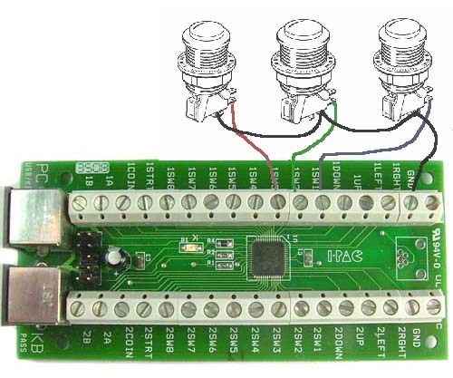
Connect one side of each switch to the screw terminals as indicated on PCB. "Daisy chain" the other side of all switches together and connect to either of the "GND" terminals on PCB. Some micro-switches have 3 connections – only use the ones marked "NO" and "COM". Don't connect anything to the "NC" tag. Below is a diagram showing an example of 3 joystick micro-switches connected to inputs on the I-PAC board.
The
gauge of wire used is not
critical. Any insulated stranded
wire will do providing it is thick enough to be gripped by the screw
connectors. The wire we supply in our wiring kit is 16 X 0.2 mm.
You can connect more than one switch to one I-PAC input, to perform the
same function. For example you might want to have side flipper buttons
connected to the same inputs as fire buttons as these are used in
different games. This applies to joysticks too. You can connect a 4 and
an 8-way stick to the same inputs. (But check our 4-8 way switchable
sticks though!)

The I-PAC 2 and I-PAC 4 use screw connectors for the controls:
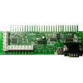
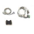
The Mini-PAC and I-PAC UIO use a supplied wiring harness. The harness comes in two sections. There is a "daisy-chain" ground harness and a 32-way switch harness.
The first step is to connect the male end of the black ground harness to the black wire on the main harness. Then connect to every switch. The example below shows 3 connected switches:

Plug one end of cable into the USB connector and other end to motherboard USB connector.
Start windows. Windows will detect the device and automatically load drivers. The drivers for this device are already within Windows. There are no Ultimarc drivers for the I-PAC.
Boot PC and
run a text program such as Notepad.
Observe the LED on the I-PAC should be ON in normal use. If there is a
failure detected during power-up, the LED will flash a number of times
then stay OFF.
Press various player 2 buttons (some of the player 1 buttons are mapped
to non-displayable codes such as ALT so best to use player 2). You
should see characters displayed, just as if they were typed on the
keyboard.
This is done using WinIPAC V2. For full instructions, click the Configuration Utility tab.
I-PAC boards support left/right mouse buttons plus game controller buttons, volume up/down, power, sleep and wake, in addition to keyboard keys. Extensive macro support is available.
Pressing and holding 1player start enables shift mode with access to the following keys (when "MAME" setting is used):
2 player start =Esc – for jumping back to the menu
Joystick left =Enter – for running games in Windows and for MAME game config menu
Joystick right =Tab – for entering MAME config menu
Joystick up =~ - for entering MAME volume/gamma menu
Joystick down =P MAME pause key
1
fire (button 1)=5
–
for
simulating coin insert.
The above shift keys can be changed/turned off as required if the board
is programmed.
MAME HINT: to get past "Type OK to continue" prompt, just move joystick left then right.
KEYBOARD: PC should pass BIOS keyboard self-test with or without a normal keyboard connected. The unit is capable of being used in a closed arcade cabinet with no additional keyboard or controls and motherboard booting into an emulation menu. If an auxiliary keyboard is connected it can be used fully and even used during gameplay alongside your control panel.
USB DOS SUPPORT : Most PCs support a USB keyboard in DOS mode so I-PAC in USB mode MAY work in DOS. (USB keyboard support may have to be enabled in the BIOS). HOWEVER: many BIOSes have poor USB support which prevent use for gaming, as the response is too slow. USB is intended for Windows use, either in a "DOS box" or a windows application.
USING TWO I-PACs TOGETHER : Two boards can be used for doubling the number of inputs. Each board can be individually programmed with the required code set, then the two boards can be connected together as above.
WIRING TWO JOYSTICKS TO THE SAME CONNECTION : This is fine, and is often done when using a dedicated 4-way joystick alongside an 8-way. Both joysticks could be wired to the Player 1 inputs. They will both perform the same function of course.
The UIO board has 48 total input connections. 32 of these are on the main harness and 16 on the pins at top left and right.
Some of these pins can be used for trackball and spinner but these are deducted from the total 48. Spinner uses two and trackball uses 4. When these devices are connected and configured in WinIPAC, these pins cannot be used for switches.
Spinner shared with P4 L-R
Trackball shared with P3 L-R-U-D.
These pins form a dual-purpose interface. The function is configured in the "config" tab in WinIPAC.
There are 2 modes:
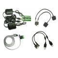
Expansion
Interface Disabled:
In this mode, an Ultimarc U-Trak
trackball and SpinTrak spinner can be directly plugged into the header
pins. The wire colors are marked.
Expansion Interface Enabled : In this mode, one or two Ultimarc Xbox360/PS3/Xinput converters can be plugged into the header pins. The wire colors are marked.
General Approach:
Remember that in its as-delivered mode the I-PAC emulates a keyboard. So if you bear this in
mind, you can use any program that displays text to test the response
with certain limitations. Notepad or the DOS prompt can be used for
example. You can connect a short piece of wire to GND and use the other
end to touch onto various input connections, and characters should be
typed on the screen. Bear in mind, though, that the default MAME
configuration includes many non-printing keys such as ALT, CTRL and the
arrow keys, so trying the player 2 inputs is best as these are all
printable characters.
But Notepad or DOS cannot tell you whether an input is "stuck" though so is not a complete test. For Windows, the best test is the Passmark keyboard Test which we can recommend downloading. It's a 30-day trial version but hopefully you will have it working by then!
Problem: Player 2 buttons 5 and 6 not working.
This is not an I-PAC problem! By default, MAME does not have these
buttons assigned to any keycodes. Just go into the MAME controls menu
(press tab in a game) and assign them. Button 5 is "I" and Button 6 is "K".
Problem: No shift functions work.
Part of the shift function design means that to avoid "stuck" keys,
shift functions are disabled when any key is pressed. So loss of shift
functions means you have a shorted or stuck switch.
Problem: Erratic behaviour of joystick directions. Shift functions not working. "Stuck" keys.
A very common cause is connection of the inputs to the "NC" contact on the switches instead of "NO". See the "no shift functions work" heading above for more info. This type of problem usually occurs when a large number of switches are incorrectly connected. The self-test LED will indicate this problem by flashing at power-up then staying off.
Problem: In USB mode, the I-PAC was not detected properly once before and now I can't get it out of this state.
You will need to remove it from Windows and let it re-detect. Go into Control Panel, System, Device Manager, Hardware. Open up the USB controller by clicking on the plus sign next to it. Under this heading will be displayed all the USB devices. Right click on all devices one by one except the controller itself and Root Hubs and select"uninstall". Now unplug and re-plug the I-PAC. It should be re-detected.
Problem: In USB mode, it is only detected as "Unknown Device" or "device has a problem".
Under certain conditions, shorted inputs can cause this, or inputs that are held at 5 volts. This may happen either because of a wiring error (see steps for checking this, above) or the I-PAC inputs being connected to something other than an open-circuit switch. If you need to connect non-switch devices please email for advice.
Problem: Keys intermittently sticking in one direction.
This is usually not an I-PAC
problem. If you check the I-PAC
installation using the
PassmarkKeyboard Test you
will probably find that this works fine and you may need to look
elsewhere on your PC installation such as some errant software
consuming PC resources.
Performing a USB Device Reset
Windows 7 and later cache information about all USB devices which is not refreshed when the device is unplugged/reconnected. This can cause issues with devices appearing not to work. This process is always required when firmware is changed from versions which support game controller device, to versions without game controller support or vice-versa.
To reset the device settings, open Device Manager. A quick way to do this is to click the Windows button and in the "search programs" enter:
devmgmt.msc

- Expand the "USB Controllers" entry
- Find the "Composite Device". There may be more than one. There is no harm in applying this to all of them with the exception that a keyboard with integrated trackball might be one of them and this will prevent any further use of the trackball if uninstalled.
- Right click on the Composite Device and "Uninstall" it.
- At the the top select "Action", "Scan for New Hardware". Alternatively, if you have "lost" your USB mouse, just unplug/reconnect it.
When a shift button has been assigned, pressing and holding this button causes the "SHIFTED" code page to be used. The way this works is not the same as defining "key multiple" in an emulator.
To explain this, consider the following example which is part of the
standard I-PAC code set in non-programmable mode (and can of course
also be set up in programmable mode)
For example say "Start 1" is the shift button and "Player 1 Button 1" is "Coin 1" in the shifted codes. Now if you set this as a key multiple in an emulator, you could generate a coin insert by pressing these two buttons together. BUT you would also send the code for the first button you pressed. Imagine you are starting a game and have one coin insert already done and you want to play a 2-player game which needs two coin inserts. You press the key combination again to send another coin. Unfortunately what may happen is that a one-player game will start as you have pressed "start1" as one half of the coin key combination!
How does the I-PAC get around this? When you press the "Start 1" (shift) button nothing happens immediately. The I-PAC waits to see if you are going to press another key at the same time. If you do press the "Player 1 Button 1" the shifted "Coin 1" code is sent. If you don’t press any other button the "Start 1" code is sent when you RELEASE the "Start 1" button. So you don’t get any unwanted key codes.

Features
- Configures each pin of the board as the correct device type, ie keyboard, gamepad, analog, mouse, volume/power.
- Displays a pictorial representation of the board
- Fully real-time interactive. Reads and write board configuration "on the fly"
- Can be run in command-line mode or GUI
- Read/Save configuration to a file
Running from command line
This program can be run "invisibly" from a command line by simply appending the name of an already-saved IPC (config) file:
Winipac.exe <name of IPC file>
This will load the configuration specified. This will also cause a mode change if needed, if using multi-mode firmware. There is more on the "Multi Mode" product tab. Note the IPC file must be accessible by using its full path or saving it in the WinIPAC install folder.
Operation
PIN drop down
This displays the selected pin you are configuring. You can select pins from here or from the main graphic.
NICKNAME
You can type text in here which will remind you of which device this pin is
connected to. The test is saved with the configuration (on the PC only)
and is not sent to the board.
FUNCTION area
Here you configure the selected pin as the required device type and
assign values to it.
You can select one of the radio buttons to define the pin as the following:
- Switch (which includes keyboard key, gamepad button and mouse buttons)
- Trackball/Spinner (includes optical steering wheels etc). This is only relevant to certain pins on the Ultimate I/O board.
NOTE: Trackball/Spinner uses 2 pins per axis. The partner pin will also automatically be assigned. You can select X, Y or Z (wheel) axis.Trackballs use two axes (4 pins).
Only the appropriate pins on the top two smaller connectors on the I-PAC Ultimate I/O can be assigned as trackball and spinner. It is recommended that you assign trackball on the left connector and spinner on the right otherwise you cannot use the special connectors for the U-Trak or Spintrak devices. The connectors for these devices are not unique. They use two or 4 of the total 48 input pins available.
The I-PAC 2 and Mini-PAC also support trackball and spinner but these use dedicated pins.
Detail Configuration Example (Switch)
The switch is connected with one terminal to the required pin and other terminal to GND.
Select the pin by clicking on require pin in the graphic area.
Select "switch" radio button in the function area.
You now can select the control type eg whether keyboard key,
mouse button or gamepad button.
In the primary drop-down all possible keys are available plus macros defined separately (see later). Note that the I-PAC sends key scan codes just like a keyboard. It does not send characters so has no concept of upper/lower case. An upper-case key is a macro consisting of the Shift key plus the required character.
If required, you can select a secondary keycode. This is sent instead of the standard code when the I-PAC shift button is held. (This is by default the Start1 button but can be changed).
There is no need a secondary code unless you wish to use shift feature.
Macros
To assign a macro proceed as follows:
- Click on the MACRO tab
- Click NEW In the drop-down box, select the first character of the macro
- Click "Add Entry"
- In the drop-down box, select the second character of the macro
- Click "Add Entry"
- Repeat above 2 steps to add further characters
- Click "Add Macro".
- Return to the main tab. Select the macro in the drop-down when configuring the required pin.
Variable
De-Bounce Delay
In the "Config" tab, the setting can be changed to 4 values as required. The default is the "standard" setting.
This value affects the rate at which the SAME input can be re-activated. Setting a low value will allow faster repeat of presses of the same button, but may also cause unwanted key repeat caused by switch bounce.
This is a specialized setting and should only be changed following testing with the specific switches being used. It does not affect overall performance because it only affects repeated action of the same input.
Dual Board Usage
This applies to the Ultimate I/O when one board has the standard firmware and a second board is connected with the "ID#2" firmware.
There is a command-line switch /2 which when used causes the board to skip the first board when detecting boards on startup.
This can be used in various ways. One method would be to copy the entire application to a different folder so you have two versions. Then edit the shortcut to the program to add the /2 switch.
Another way would be to use only one version and either apply the switch or not. Care would be needed when saving and loading IPC files.
If both boards are required to be reconfigured on the fly, a batch file would have two lines, each specifying a different IPC file and one with the /2 switch.
Upgrading Firmware
The firmware upgrade is a two-stage process.
First, the board is placed in firmware upgrade mode. Also a driver is installed on-the-fly if this is the first time an upgrade has been done on the PC.
Then, a program called UUPLOAD performs the upload of the firmware to the board. This program will not detect the board unless it has been placed into upgrade mode from within WinIPAC.
The following steps need to be followed:
- Run WinIPAC as administrator (right click and select "run as administrator")
- Ensure the board is detected and click "File, Firmware Upgrade".
- OK the prompts. The board should reset and change to "Firmware Upgrade Device" (If you have Device Manager open you will see the new device appear under the USB Controllers entry.
- A program called UUPLOAD.EXE should automatically start. If the process fails you can manually run this program if you have a "Firmware Upgrade Device showing in Device Manager
- Select the firmware file
- Uploading to the board
should take approx 2-3 minutes. After that, the board should reset
again and re-appear as a keyboard, mouse and game controller and be
ready for use.
Note: If the process will not work, you can try manually pre-installing the firmware upgrade driver by downloading the installer from this page which also contains additional information on the process and how to recover from failures.


The units were designed around MAME and normally you would use a front-end menu for selecting games. But of course, as the I-PAC emulates a real keyboard (without all the drawbacks) you can use any PC application which uses keyboard input.
Yes. You can use the fully programmable code sets of I-PAC to customise for any emulator or other application. Several popular front-end menus even have integrated support for downloading I-PAC codesets on-the-fly.
NO. Using the key-code programming is entirely optional. When the board is shipped, all codes are automatically assigned to MAME standard keys. As many people have found, this makes installation very quick and easy.
One method is to hack a keyboard, i.e. connect all the controls to the keyswitches so each button appears as a key. This is pretty unsatisfactory for several reasons: It takes ages to wire up as 2 wires need to be run to each switch.
Most arcade cabs have one side of all switches commoned so you have to re-wire everything.
Key Ghosting: This happens because of the matrix nature of keyboard encoders.
Extra buttons: With this solution, with some emulators you have to have extra buttons on the cabinet for functions such as "escape", "insert coin" etc. Nobody likes drilling extra holes in their nice original arcade cab!
Speed: Keyboard encoders use a scanning method. So each key is checked in sequence for a press or release. I-PAC does not use a matrix or scanning.
Shifted function keys will do various functions ie press "1 player start" and "fire" and you will insert a coin. Press "1 player start" and "2 player start" and you will jump back to the menu. You can also use the MAME game config menus with shift buttons, ie tab and enter are shift joystick right and left. The 1 player start button is always the shift button if you are using the standard MAME codes. In programmable mode you can assign any input to be the shift button and you can program all of the buttons to have shifted codes. The unique feature of the shift function is that it requires no dedicated extra button.
When the board is shipped it contains all standard MAME codes including the shift codes mentioned above. If you only ever use MAME and want a quick and easy install this will probably do for you. But if you need to, you can re-program as required, including "on the fly", and the board will remember your new settings.
You may find you need to change the assignment of keys for other emulators or maybe you don't want to have the shift functions of the MAME code set. The code set can be changed using the WinIPAC utility.
Normally you would install and test the board before getting into programming.
Will it work on a MAC?
Yes the I-PAC will work on a MAC with USB. There is even a Mac version of the programming utility.
Will it work on a Linux host including Raspberry Pi?
Yes the I-PAC will work on a Linux host. There is third-party Linux programming utility support (see Downloads page).
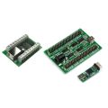
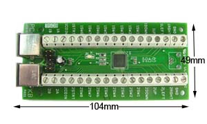
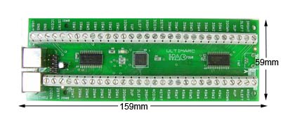
What is the size of the board?
Dimensions shown below. Height is approx 17mm.

Recommended Wiring Procedure
Arrange the large switch connector on your left with the wires running towards the right, as shown in the right side of the diagram above, with the white polarising key at the bottom.
Working from the bottom of the connector, first connect the BLACK wire to the male connector on the ground harness.
Separate the rest of the wires into 4 groups. Start each group with the brown and red wires (bottom) and end with the purple and grey wires (top). You can ty-wrap the 4 groups close to the connector if you wish, or just lay the groups across the panel.
Now the wires from each group can be connected to the correct switches as shown on the diagram above. The table below may help, as this presents the connections in switch order and shows only the commonly-used switches
Then connect the ground harness to the other contact of each switch. Run along the controls in the most convenient path. You can miss out a connector if you need a longer routing as there are spares. Cut off the extra length.
If you are using the trackball/spinner harness connect the three other plugs to the trackball and spinner as shown and connect this to the board.
Ty-Wrap all wiring for neatness.
Reversing Trackball Axis
If you find one of the trackball axes moves "backwards", the resolution is to swap the X1 and X2 wires over (or Y1 and Y2). To do this, consult the diagram above and locate the correct pair of wires, at the main 30 way plug. The wire and contact can be removed from the black housing by carefully lifting the small tab on the side of the housing and pulling out. Swapping the pair of wires will reverse the direction of that axis.
Connecting Mouse Buttons
Mouse buttons can be connected to the trackball/spinner harness connector. These are not fitted as standard. They should be located as shown in the diagram above. You can swap over two spare wires from your switch harness. The wire and contact can be removed from the black housing by carefully lifting the small tab on the side of the housing and pulling out. Alternatively use two wires from the optional extension wire pack.
Keycodes, Programming and other Information.
All of the information on the I-PAC applies to the Mini-PAC. The default keycodes are the same, all programming information applies inclusing use of the WinIPAC utility, so check out the I-PAC pages for further information.
Troubleshooting Tips
All of the information on the I-PAC applies to the Mini-PAC. The LED indications are the same, all troubleshooting information applies, so check out the I-PAC pages for further information.
I-PAC Firmware version 50 Enhanced Modes
The new Mini-PAC 4 supports instant button-controlled mode switching.
Two buttons can be connected to these arrowed pins:

- Pins enable instant switching from keyboard to Xinput mode and back.
- The switching will be to the default Xinput codes only, not any custom map.
- We are open to any suggestions for changes to the defaults and can produce custom firmware if required.
- Please note on this board (and I-PAC 4), WinIPAC cannot send/receive map data when in Xinput mode. Its still possible to create a customised Xinput map for semi-permanent use (see further down).
- Traditional I-PAC keyboard mode unaffected. This is still the shipped default.
- Device mode can also be switched to Dual Directinput Game Controller or Dual Xinput Game Controller. I-PAC 4 and Mini-PAC 4 support 4 game controllers.
- Device ordering will not change.
- These modes appear as entirely different USB devices so there is no mixed-device confusion which causes issues in Retropie.
- Selected mode is maintained after power off/on.
- Standard Dinput and Xinput Game Controller modes are preset for ease of use without any configuration.
- For advanced users who wish to create custom Game Controller configurations there are customisable game controller modes.
- Modes can be switched by pressing Start1 (or user-set alternate I-PAC shift) and holding this, and Player 1 button 1 through 5, for 10 seconds.
- Modes can also be switched by loading an appropriate config file using WinIPAC including “invisibly” via a command line. This is the recommended method. (excluding I-PAC 4 and Mini-PAC 4 Xinput)
These modes apply to Player 1 and 2 controls on I-PAC 2/Mini-PAC/UIO and all 4 players on I-PAC 4 and Mini-PAC 4.
I-PAC Connection |
Mode 2 |
Mode 3 |
Mode Switching |
|
Left |
Dpad Left |
Dpad Left |
|
|
Right |
Dpad Right |
Dpad Right |
|
|
Up |
Dpad Up |
Dpad Up |
|
|
Down |
Dpad Down |
Dpad Down |
|
|
SW 1 |
Button 1 |
A |
Mode 1 (Keyboard User Set) |
|
SW 2 |
Button 2 |
B |
Mode 2 (Dinput Preset) |
|
SW 3 |
Button 3 |
X |
Mode 3 (Xinput Preset) |
|
SW 4 |
Button 4 |
Y |
Mode 4 (Dinput User Set) |
|
SW 5 |
Button 5 |
Left Rear |
Mode 5 (Xinput User Set) |
|
SW 6 |
Button 6 |
Right Rear |
|
|
SW 7 |
Z Left |
Left Trig |
|
|
SW 8 |
Z Right |
Right Trig |
|
|
COIN |
Button 7 |
BACK |
|
|
START |
Button 8 |
START |
|
|
A |
HOME |
||
|
B |
Button 7 |
BACK |
|
|
START plus P1 RIGHT |
HOME |
||
|
START plus P1 LEFT |
BACK |
||
Using WinIPAC, any input can be configured to any control including keys, power/volume, gamepad (Xinput or Dinput) across both players.
When this is done, keys configured as keyboard keys will respond in Mode 1, Keys configured as gamepad keys respond in modes 4 and 5.
Note this feature allows the entire 2-player panel to be configured as a one-player game controller if required, implementing every possible control.
Using WinIPAC, any key can be configured as mouse left or right button, Sleep, Wake, Vol Up, Vol Down. These will function in modes 1 and 4. (not Xinput).
When powered on, the LED will stay lit once the board has passed self-test and detected by the host system.
When switching modes, the LED will flash off, the number of times according to the mode number selected, after the 10 second period.
This is intended for use when WinIPAC is used for downloading configurations on the fly. This is the recommended method of mode switching if it is required to regularly switch modes.
Mode will switch automatically under the following conditions:
- If a keyboard-only configuration is downloaded and the board is currently in gamepad custom mode 4 it will switch to keyboard mode 1.
- If a gamepad-only configuration is downloaded and the board is currently in keyboard mode 1, it will switch to gamepad custom mode 4.
- If a gamepad-only configuration which includes an Xbox Home key is downloaded and the board is currently in keyboard mode 1, it will switch to gamepad custom mode 5.
Owing to the limitations imposed by the MS proprietary Xinput protocol, the following are NOT supported in Xinput modes but are supported in keyboard and Directinput modes:
Mouse buttons
Volume up and down buttons
Power, sleep, wake buttons
LED control (I-PAC Ultimate I/O only)
No trackball/spinner support
WinIPAC configuration changes take slightly longer in Xinput mode.
These boards supports quad Dinput and Xinput game controllers using firmware version 1.56. This is available in the firmware ZIP on our download page.
When using WinIPAC, all custom settings for player 1 are automatically mirrored to the player 3 controller and all settings for player 2 are mirrored to player 4.
Please note an important limitation which applies only to the I-PAC 4 and Mini-PAC 4 when in Xinput mode:
WinIPAC cannot be used for reconfiguring controls or switching modes on the fly when in Xinput mode.
To create a custom Xinput configuration proceed as follows:
If the board is in Xinput mode, reset it to Dinput mode by using the hotkey Start1+P1SW4 for 10 seconds. If this does not work use the "backdoor" by holding in P1SW1 while plugging in USB.
If necessary, load in the default Dinput IPC file which can be found in the defaults sub-folder of the WinIPAC install.
Change settings as required. For Xinput, one of the controls must be set to HOME.
Save the file as an Xinput configuration.
Click "File, Force Board Reconfiguration". The board should switch to Xinput mode using the custom configuration.
Mode switching can be confirmed by observing the on-board LED or “Devices and Printers”, the USB connect sound or other indication on the host.
If hotkey mode switching fails to work, check that Start1 (or another connection) is configured as an I-PAC shift control. If this feature has been removed in WinIPAC, hotkey mode switching will not work. Any stuck/shorted controls will also inhibit mode switching.
The board can be rest back into keyboard Mode 0 by pressing and holding the P1SW1 button on power up. This will work irrespective of the current board mode or input configuration. Note it must be a hard power-up or plug-in of the USB cable.