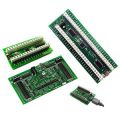
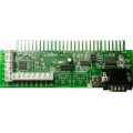
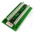
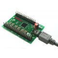
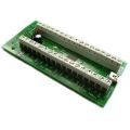
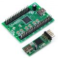
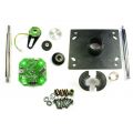
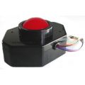
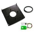
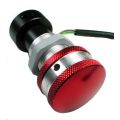
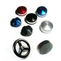
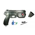
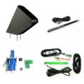
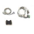
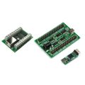
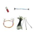
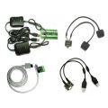
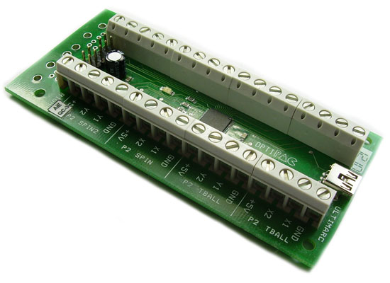
The Opti-PAC (Optical Interface for Pc to Arcade Controls) is an interface for easily connecting optical-type arcade control devices including trackballs and spinners to a PC for use with emulators such as MAME.
Features:
- One USB cable handles up to two trackballs and 4 spinners/rotary joysticks.
- No external power needed.
- The active control (trackball or rotary) is automatically selected.
- Supports buffered controls (Happ, Ultimarc U-Trak) or unbuffered (Suzo, Wico, Ultimarc 2 1/4), high or low polarity.
- Configurable via software utility for active high/active low.
- Full-Speed USB Interface. 16 Bit data.
- Will work alongside PS/2 or USB mouse if required.
Optical Controls Technical Info:
The two sensor outputs are compared with each other to generate movement direction.
Therefore the interface requires two parts:
A voltage supply for the LED.
Inputs for the two sensors.
The OPTI-PAC has voltage outputs for the LED and the 2 inputs for the two sensors. It takes all voltage needed from the USB port.
A dual-axis device such as a trackball has all the above multiplied by two. Two LEDs, two pairs of sensors. So the board has two independent circuits for the X and Y directions. These two circuits can either be used on the same dual-axis device or separate single-axis spinners.
Connecting the Ultimarc/STC 2-1/4 inch trackball or Ultimarc U-Trak
This is supplied with connecting cables. There is one cable per axis. The location of the two plugs is described in the table looking from the top.
The GND and +5V from both plugs go to the same GND and +5V connections on the Opti-PAC.
| Plug at "12 o'clock" position | Plug at "9 o'clock" position | ||||||
| Black | Red | Yellow | Green | Black | Red | Yellow | Green |
| GND | +5V | Y1 | Y2 | GND | +5V | X2 | X1 |
| Black (2 wires) | Red (2 wires) | Purple | Blue | Yellow | Green |
| GND | +5V | X1 | X2 | Y1 | Y2 |
There are two +5V and GND wires. These can both be connected to the same +5V or GND connection.
The Happ trackballs have a green ground wire. This is to prevent static buildup and can be connected to any convenient ground point.
Plug USB cable into the connector on the board and connect to the PC USB port. The PC will auto-detect the device and install a standard mouse driver. (Actually it installs two mouse devices)
Windows
Buttons.
If the horizontal and vertical axes are reversed, swap the "X" wire connections with the "Y" connections.
If either of the horizontal or vertical movements are backwards, swap the X1 wire with X2 or swap Y1 with Y2 as appropriate.
| Vert 1 | Vert 2 | Vert 3 | Vert 4 | Horiz 1 | Horiz 2 | Horiz 3 | Horiz4 |
| +5V | Y1 | Y2 | GND | +5V | X1 | X2 | GND |
There are two models of Suzo trackball: Active High and Active Low.
These are the part numbers:
29-0210: Active Hi White ball
29-0210-2: Active Hi Red ball
29-0230: Active low White ball
29-0230-1: Active low Red ball
See above for button connection and software.
Connect as above to the connection group marked "P1 Rotary". A spinner uses only one axis so connect this to the X1 and X2, +5V and GND only. A second single-axis device can be connected to Y1, Y2, +5V and GND. The selection of which axis to be used in each game (and therefore which control) can be made in MAME.
Connection of devices to Player 2 is identical to Port 1. The automatic device switching described above applies to Player 2 also. Player 2 uses a second USB mouse device (although this is via the same cable as Player 1). Current MAME versions support independent mouse devices.
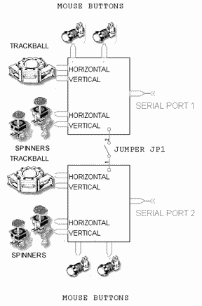 Any optical wheel type sensor type device can be connected to the Opti-Pac. In order to connect other devices this section contains further information on the connections.
The two sensors correspond to the X1 and X2 inputs of the Opti-Pac, or the Y1 and Y2 for vertical. On a trackball the horizontal and vertical axes are two completely separate circuits.
A spinner is a single-axis device so simply has only one of these two identical circuits. This means two spinners require the same number of inputs as one trackball.
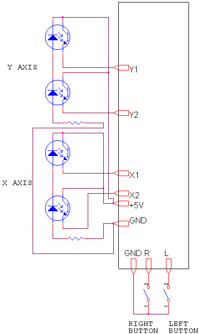
| X1,X2 Y1,Y2 | Inputs from the phototransistors on the optical sensor |
| +5V | Positive voltage supply to the optical sensor LED. Note that all connections marked +5V are connected together on the board and any one can be used. |
| GND | Return from the optical sensor LED. Note all connections marked GND are connected together on the board so any one can be used. |
| Port n Button L | Left mouse button input. (connect other switch contact to any GND) |
| Port n Button R | Right mouse button input. (connect other switch contact to any GND) |
The optical sensor connections are grouped into four control groups. Each of the four groups can accept one trackball or two single-axis devices such as spinner, rotary joystick etc.
There is no difference in the function of the "Trackball" groups and "Rotary" groups. The different names are for convenience only.
The two control groups marked "P1 Trackball" and "P1 Rotary" are routed to Mouse 1 (Player 1).
The two control groups marked "P2 Trackball" and "P2 Rotary" are routed to Mouse 2 (Player 2)
If your device is "Active High", it will pull the outputs to 5 volts, or leave "open" depending on the wheel position.
The Opti-PAC can be configured to handle Acrive-High devices using a simple software utility. Just click on the check-boxes for the inputs you need to be set to active-high.
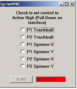
Click here to download this utility. Unzip into a folder (2 files).
Troubleshooting Trackball Connection Problems.
If you have no trackball movement, try the following.
Remove one trackball optical sensor PCB from the trackball. These slide out after removing a small round retainer with a tab.
The track side of the PCB should look like this. If it is the "special" type for Mini-PAC it will have two extra resistors added to this side.
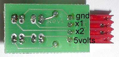
With a voltmeter check the following with the board still connected to the Opti-PAC.
Black probe on GND, red on 5 volts. This should read 5 volts.
If this does not read 5 volts, check the wiring from the PCB locations to the 5V and GND tags on the Opti-PAC. Use the continuity setting on the meter, after disconnecting the Opti-PAC from the PC (ie remove power)
Black probe on GND, red on X1
The voltage should be approx 0.5 volts. Then place an object in the slots on the sensors on the other side of the board. The voltage should rise to approx 4.5 volts.
Voltage stuck low: this indicates a wire problem between the PCB and the Opti-PAC terminal, or Hi/Lo jumper not set to LO.
Voltage stuck high indicates a problem with the optical sensor or a wire connected to the wrong terminal on the Opti-PAC
Repeat the above for the X2 connection.
Repeat all of the above tests with the other axis. You might be able to isolate the problem by swapping PCBs or cabling.
![]()
This page is for people who have some kind of mechanical device such as a spinner already built and want to add the electronics to connect it to the Opti-Pac Plus. Only the electrical connections are covered here, you'll still have to work out a method of mounting the sensors or PCB to your mechanical device and you will need a spoked disk mounted on the shaft. Two methods are covered: Using a Happ Controls Optical PCB and Using a pair of Opto Switches.
This is what the PCB looks like and shows the connections. Simply wire up each pin as shown on the picture to the corresponding connection on the Opti-Pac.
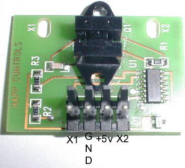
This method uses a pair of standard opto-switches. These can be obtained from electronics supply stores. The cheapest type will do, which simply have a LED in one side and a photo-transistor on the other. They usually cost less than $1.
In the US try Digi-Key. An example part number is QVB11334. You will also need to buy
cheap klonopin online a 220R resistor.
The switches will be marked "E" and "S" on each side. the "E" side=Emitter and "S"="Sensor" (may also be "D"=Detector). First glue the sensors together with the "E" marks alongside each other as shown below: Then turn over the assembly. IMPORTANT: The pictures below show the assembly with the "E" sides at the TOP.
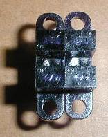
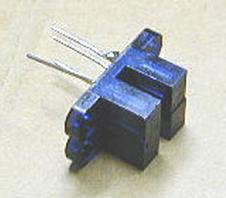
Solder a 220R resistor as shown between the two diagonally opposite pins on the right-hand sensor. Solder the lower left pin of the right-hand sensor to the lower left-hand pin on the left-hand sensor (bend the pin around).
Solder the top left pin of the right sensor to the top right pin of the left sensor. (Hopefully the picture is easier to understand than this description!). Cut off any protruding pins of these two you just linked.
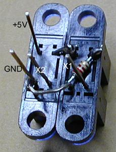
You should end up with four protruding pins left. Connect these to the Opti-Pac Plus. The picture shows push-on connectors but you could just solder wires to each of the four pins. Some shrink-fit sleeving finishes off the job. For this configuration the jumpers are set to "A/LO" on the Opti-Pac.
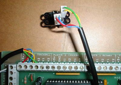
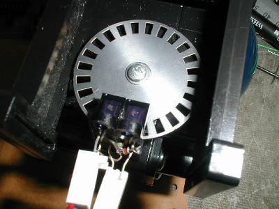
Now mount the assembly on your mechanics by whatever method works. The optical wheel should be positioned centrally in the notch of the sensors.
![]()
What controls can I use?
The Opti-Pac Plus supports all controls which use an optical wheel sensor system. This includes trackballs, spinners and rotary joysticks of all makes. It supports buffered types which include Happ devices, unbuffered (Suzo), high or low polarity. Don't worry if you don't know what these terms mean, there are easy wiring instructions for the various types of controls.
Do I need a power supply?
No. Power comes from the USB port.
What about mouse buttons?
Inputs are provided for mouse buttons. These inputs can be wired up together with I-PAC button inputs so that control panel buttons can perform dual function: mouse buttons and normal key-type inputs. So you could use your trackball as a mouse with two of the control panel buttons working as mouse buttons and also have these buttons work in games via the I-PAC.
What does the labeling on the input connections mean?
The input connections are labelled Player 1 Trackball, Player 1 Rotary and Player 2 Trackball, Player 2 Rotary. There is no difference in functionality between a Trackball input and a Rotary input. The different terms are used only for convenience. Each of these four inputs has two axes. This means each of these four can handle one trackball or two spinners or two rotary joysticks. There are also power connections. Multiple power connections are provided for ease of wiring, they are actually commoned on the board.
What happens if I have (say) a trackball connected to Player 1 Trackball input and a spinner connected to Player 1 Rotary input. How does the board know which one I actually want to use to play the game via Player 1 mouse device?
The movement of both controls are simply "added" together to determine mouse movement.

